

Reference Links
How It Works: Siemens Automatic Tool Changer (ATC)
VMCsi - Reference ATC Magazine
VMCsi- Clearing ATC Fault Guide
VMCsi - ATC Arm Manual Movement Guide.
VMCsi - Set Orientation Angle & Tool Change Height
VMCsi - BT40 Option - ATC Arm Replacement
Alarm Sequence
In Expert Deployment v01.01.17 (PLC version 05.04.19), additional alarms were introduced to monitor the tool change process. While the alarms do not follow a strict numerical sequence, they trigger in the following order (from bottom to top in the image):

700940 – Tool Change Active Banner
- This banner is displayed to the user during the tool change process.
- While active, RESET and CYCLE STOP are blocked.
700938 – M81: Pot Down
700934 – M82: Arm Moves from Home to Spindle
700948 – M85: Tool Unclamp
700935 – M83: Arm Swaps Tools
700949 – M86: Tool Clamp
700936 – M84: Arm Moves from Spindle to Home
700937 – M80: Pot Up Active
All alarms are automatically cleared at the end of a successful tool change operation. If the ATC faults during the tool change, the last displayed alarm indicates where the fault occurred. This can help troubleshoot the cause of the fault.
Alarm Context Help
In Update v01.01.23 (PLC version 05.04.36), alarm context help was implemented to provide troubleshooting guidance for some alarms.
Alarm 700938 – M81 Pot Down Failure
The alarm will be cleared when pocket is down, RESET or ESTOP is pressed, or pocket does not go down for more than 2.5 seconds after it is commanded to move. Check pocket down output Q41.4, check the air pressure, and pocket down sensor input I34.7.
Alarm 700948 – Tool Unclamp Input Issue
If the alarm is not cleared, I33.7 (tool unclamp) input to the control may not be set to high. Check whether I33.7 is high when tool is released and low when tool is clamped. If the input is not behaving correctly, check the tool unclamp switch mounting on Z head assembly.
Alarm 700949 – Tool Clamp Input Issue
If the alarm is not cleared, I33.6 (tool clamp) input to the control may not be set to high. Check whether I33.6 is high when tool is clamped and low when the tool is unclamped. If the input is not behaving correctly check tool clamp switch mounting on Z head assembly.
Alarm 700937 – M80 Pot Up Failure
The alarm will be cleared when pocket goes up, or pocket does not go up 1.5 seconds after M80 is issued. Check pocket up output Q41.5, pocket up input I34.6, and air pressure.
Clamp Sensors
If you navigate to [Diagnostics] → [Trak Diagnostics]. At the top, you’ll see the following inputs:
- toolAtClamp-I33.6
- toolAtRelease-I33.7
 |
These inputs correspond to the two sensors monitoring the tool clamp and release states.
 |  |
When the green unclamp button is pressed (or when the ATC performs a tool change), the pin drops down and engages the bottom sensor. At this point:
- I33.6 → True → False (clamp disengages)
- I33.7 → False → True (release engaged)
If the VMCsi encounters tool change issues regarding Error 700949 – M86: Tool Clamp or Error 700948 – M85: Tool Unclamp look into these sensors.
If the clamp/unclamp cylinder lacks sufficient hydraulic oil (SAE 10W / ISO 32), it may fail to operate completely. Since this is a closed-loop system, a low oil level likely indicates a leak—inspect the system for leaks.

Spindle Cage
The spindle cage ensures consistent tool release by creating a controlled “bump-out” motion during the unclamp process. This bump-out helps break the taper lock between the toolholder and the spindle, preventing sticking or inconsistent release.
The cage assembly is mounted to a threaded piston rod connected to the unclamp air cylinder. A reference nut at the top of the assembly sets the starting height. To begin setup, an approximate 5 mm gap should be established between the bottom of the cage and the top of the spindle’s unclamp plate. This gap can be estimated using a 5 mm Allen wrench, drill bit, or gage pin. However, this measurement is only a starting point, the actual goal is to achieve proper bump-out travel at the toolholder.
Fine-tuning the bump-out involves rotating the cage to adjust its position on the piston rod. The ideal bump-out travel is 0.015 to 0.020 inches (0.50 to 0.80 mm) at the pull stud.
 |  |
Adjustment Rule of Thumb:
- Too little bump-out → decrease the gap (lower the cage).
- Too much bump-out → increase the gap (raise the cage).
To verify proper bump-out, hold a tool in the spindle and press the [Tool Clamp] button. The tool should push downward slightly, even when light upward resistance is applied. This confirms that the drawbar is extending fully during unclamp.
Once proper bump-out has been achieved, the cage must be secured using the four M5-0.8 x 30 mounting screws. Apply Loctite 243 (blue) to each screw and torque them to 7.0 Nm (5.2 ft-lb). The top plate of the cage is self-aligning due to oversized screw holes—it will automatically center against the unclamp plate when fully clamped.
During regular maintenance or if tool release becomes inconsistent, it is important to check the torque of the cage screws. Loose screws are a common cause of poor tool release or excessive pulling force by the ATC arm. Always verify that the cage is properly secured and free of debris or mechanical interference.
Below is the 31889 assembly drawing and cross-section view of the top portion of the cage assembly. The cross section is showing the closeup details of the self-aligning connection of the cage assembly’s top plate, to the threaded piston rod of the unclamp cylinder.
 |  |
Self-Aligning Cage Top Plate
- The cage’s top plate has oversized holes (highlighted in yellow in the cross-section) for the 4 locking screws.
- These holes allow the cage to self-align with the spindle unclamp plate when it contacts it.
- After installing, lightly push/pull the cage side-to-side — it should move slightly and return to center.
Rotary Joint Installation
Reference Folder: 31577_RotaryJoint


The Rotary Joint 903-140-188-IC (TRAK P/N: 31577), also referenced as Kit 34204, requires tight tolerances to operate safely at high spindle speeds. The critical region is the "Customer Interface" section of the drawing 903-140-188-IC, which defines acceptable concentricity and perpendicularity for the rotary joint mounting surface.
Before installing or replacing the rotary joint, inspect the rear spindle interface for any wear or distortion. Damage from a failed union may push it out of spec.

If any rework is required to the spindle shaft or its rear interface, please provide the spindle serial number to TRAK Technical Support. We will coordinate with Royal Products (spindle OEM) for model-specific repair procedures.
Rotary Joint Torque Specification
Tighten the rotary joint bolt (24 mm hex) to 35 Nm, equivalent to 25.8 ft-lbs.
Inspection Procedure
18 mm Pin Gauge Fit Check
- Insert an 18mm pin gauge into the spindle’s rear locating bore.
- Diameter Spec: Ø17.995 mm +0.005 mm
- It should seat snugly to confirm the bore diameter is correct and undamaged.
Perpendicularity – Spindle Mounting Face
- Mount a dial indicator to the machine frame.
- Sweep the rear spindle face where the rotary joint will bolt on.
- Max Perpendicularity TIR: 0.005 mm (0.0002")
- This ensures the face is square to the spindle axis.
Concentricity of Locating Bore
- With the pin removed, sweep the inner wall of bore.
- Max Concentricity TIR: 0.007 mm (0.00028")
- This confirms the bore is concentric to the spindle’s rotational axis.
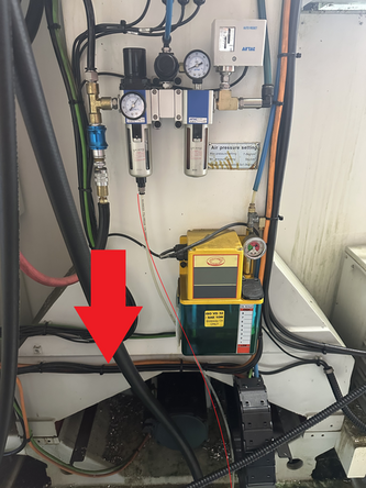
Pneumatic System
The pneumatic system powers both the clamp/unclamp control as well as ATC pot up and down.
34320-1_PNEUMATIC SYSTEM-VMCSI 7/10
34320-2_PNEUMATIC SYSTEM-VMCSI 12/14

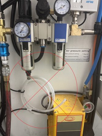
Ensure the drain hose from the air regulator is untied and routed downward to allow proper drainage.
Do not coil or leave the hose in a looped position, as shown in the second image. This can trap water and lead to sensor faults or regulator damage.
 |  |
ATC Service Mode
The ATC Service Mode is used to bring the ARM back to its home position when a tool change fails. There are two relevant service mode levels for ARM motion: Service Mode Level 1 and Service Mode Level 2.
To enter ATC Service Mode:
New PLC: Hold [Spindle Stop] and press [Feed Stop] three times.
Old PLC: Hold [Spindle Stop] and press [Feed Start] three times.
In Service Mode Level 1, the Arm respects the normal tool change sequence. When the Arm is positioned below the spindle, you must press the Tool Unclamp (green) button to release the tool before continuing with the tool change process. This ensures the Arm moves according to the expected sequence and prevents damage.
In Service Mode Level 2, the Arm ignores all normal tool change sequences. It will move as long as E-Stop is released and Z is above the safe tool change height.
Use extreme caution in Spindle Service Mode Level 2. The ARM will damage anything it collides with.
To enter Service Mode Level 2, repeat the same process used to enter Service Mode Level 1. The light on the MCP will blink faster, indicating the higher service mode level.
For more information about Spindle Service mod and clearing ATC faults, refer to VMCsi- Clearing ATC Fault Guide
ATC Cam Wheel Timing
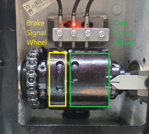
The ATC arm uses two signal wheels to control position sensing during the tool change:
- Left Wheel = Brake Signal Wheel
- Right Wheel = Cam Signal Wheel
Each wheel rotates past a fixed sensor block containing sensors S34 to S36. These sensors detect the arm’s position and trigger the next motion in the ATC sequence.
Sensor Functions
- S34 = Brake engage/release signal
- S35 = Tool Clamp/Unclamp window
- S36 = Home Position signal
- S37 = Not used on this machine.
How It Works
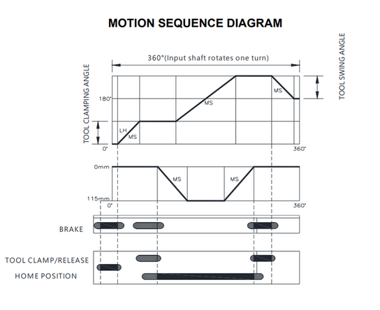
Each signal wheel has slots or notches that rotate past sensors S34–S36.
These sensors toggle on/off as the wheels rotate, signaling where the ATC arm is in its motion cycle:
Mechanical Home Position = The ATC arm is centered between the spindle and tool pot.
At this position:
- Only Tool Clamp Sensor (S35) is lit
- Brake (S34) and Home Position (S36) sensors are off
- The arrow on the cam signal wheel is typically centered between the two markings
S34 – Brake Sensor = Activates at the start and end of arm travel to engage/disengage the ATC brake.
S35 – Tool Clamp Sensor = Active when the arm is aligned with the spindle or pot, indicating it’s safe to clamp/unclamp a tool.
S36 – Home Position Sensor = Turns off when the wheel notch passes under the sensor, helping define arm timing during the rotation.
Mechanical Adjustment
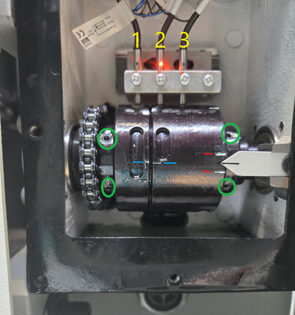
Signal Wheels and Set Screws
The wheels are secured to the arm shaft by green-circled set screws (see image):
- Left screws adjust the Brake Signal Wheel
- Right screws adjust the Cam Signal Wheel
Loosening the screws allows each wheel to rotate independently of the shaft for fine timing adjustments.
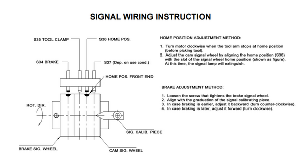
Adjusting Home Position (Cam Signal Wheel)
- Confirm the ATC arm is already in the Home Position — centered between the spindle and tool pot. This is the default stopping point after a completed tool change.
- Loosen the right-side set screws (Cam Signal Wheel).
- Turn the Cam Signal Wheel until only the center sensor (S36) is lit.
- This usually corresponds to the arrow being positioned between the two red markings on the wheel.
- Tighten the screws and verify that the sensor turns on and off cleanly as the arm enters and exits the Home Position.
Adjusting Brake Timing (Brake Signal Wheel)
- Loosen the left-side set screws (Brake Signal Wheel).
- Turn the Brake Signal Wheel slightly to shift when the brake engages during arm rotation:
- Engages too early? Rotate the wheel counterclockwise.
- Engages too late? Rotate the wheel clockwise.
- The default alignment is when the two blue markings on the signal wheels are lined up — use this as a starting reference.
- Tighten the screws and verify that the brake engages and holds properly at the beginning and end of the ATC arm motion.
ATC Motor Brake
The ATC Motor has a brake lever that must be in the down position while running. If the lever is not fully engaged, the arm can drift slightly after each motion. Depending on the motor version, the brake lever may not lift as high as shown in the picture to disable, but fully pressing the lever down always indicates the brake is engaged.
For more information on manually turning the arm via the motor, refer to the VMCsi ATC Arm Manual Movement Guide.
This video shows the arm movement with brake disengaged.
 |  |
ATC Home Sensor

The home sensor on the VMCsi tool magazine detects the metal plate on the magazine to confirm when it moves from the last tool position (e.g., Pot 24, 30, or 40) back to Pot 1.
When the sensor detects the plate (input high), the PLC resets the magazine count to 1.
If the sensor fails to detect the plate, the PLC incorrectly increments the count beyond the intended tool limit (e.g., 41 for a 40-tool ATC), causing an out-of-bounds error.
For more information regarding the home sensor go to Step 8 of VMCsi - Replace Carousel Disc

ATC Maintenance Schedule
Monthly
Inspect Pots
- Check for cracks, deformation, or elongation in the plastic.
- Verify springs and retention balls are intact and seated properly.
- Replace any pot showing wear or if tools drop/fit loosely. Use Loctite 243 on replacement screws and torque to spec.
- Pots are not repairable or serviceable
Inspect Carousel Grease
- Remove the white plastic cover and check that grease on the slideway and segmentation cam has not been washed out by coolant.
- Reapply NLGI Grade 2 grease if dry or contaminated.
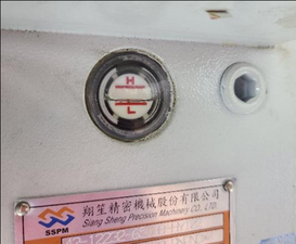
Check Cam Box Oil Level
- Inspect the sight glass; oil should be at the halfway mark.
- Top off with ISO VG 68 hydraulic oil as needed. Avoid overfilling.
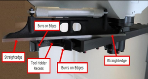
Inspect ATC Arm
- Check the arm for bends, dents, or burrs.
- Confirm smooth movement in Service Mode and look for signs of collision or binding.
Quarterly
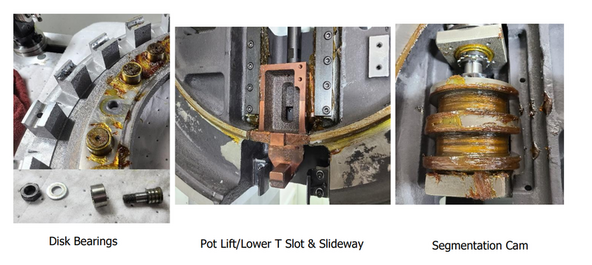
Grease Critical Components
- Carousel outer slideway
- Segmentation cam profile
- Disc bearing races
- Pot lift/lower T-slot
- Wipe away old grease and apply fresh grease evenly. Rotate carousel by hand to distribute.
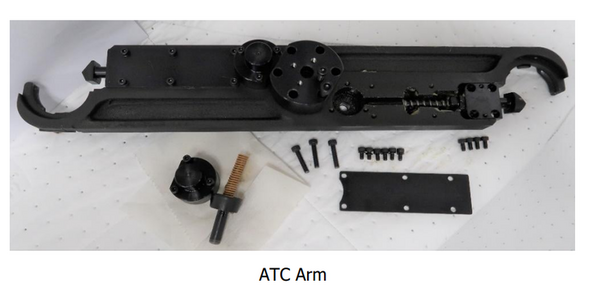
Service ATC Arm Spring & Plunger
- Remove the arm access cover to expose spring and plunger.
- Disassemble and note spring preload and orientation.
- Clean components and inspect for corrosion, wear, or binding.
- Apply high-pressure grease to spring surfaces and plunger contact points before reassembly.
- Test plunger return in Service Mode.
Annually
Deep Clean & Regrease Carousel
- Disassemble the carousel disc and clean the segmentation cam, slideway, and disc bearings.
- Regrease all carousel points and check for debris buildup.
- Inspect carousel main bearings for smooth rotation and contamination. Clean and regrease if needed.
Drain and Refill Cam Box Oil
- Drain old oil completely via the drain plug.
- Flush with clean oil if contaminated.
- Refill with ISO VG 68 hydraulic oil until the sight glass reads halfway.
0 Comments