Introduction
Replace the ATC carousel disc on a VMCsi. The bearings and the home marker move from the old disc to the new one.
Drawings 34030 and 34030-1 and the 24T-30T ATC manual are attached at the end of this guide.
Tools
Parts
No parts specified.
-
-
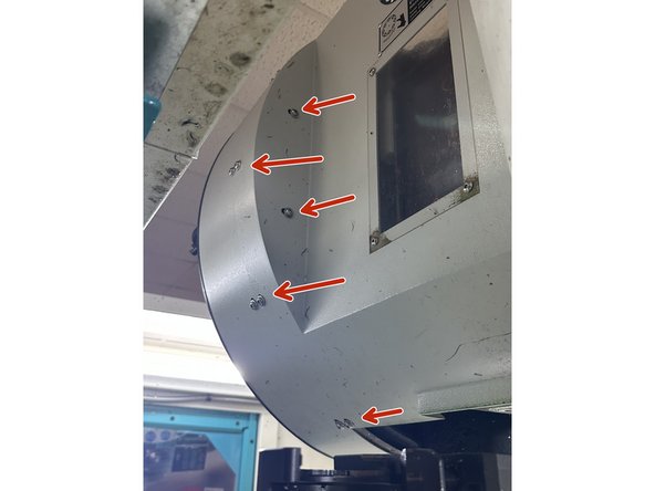
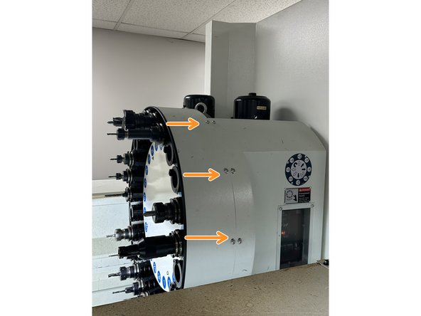
Remove the 11 hex socket screws securing the outer sheet metal cover.
-
Lift the cover off.
-
-
-
Remove the seven hex socket screws securing the gearbox cover.
-
Lift off the sheet metal cover with the viewing window.
-
-
-
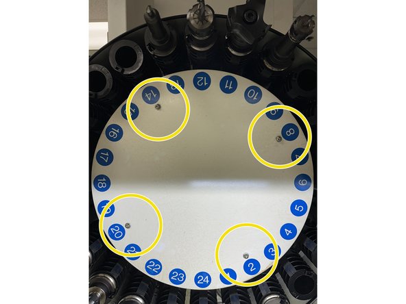
Remove the four hex socket screws securing the carousel cover.
-
Remove the cover and set it aside. If the ATC is not marked with position 1 under the cover, note the cover orientation.
-
-
-
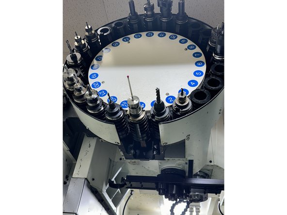
The pots come off the bottom of the carousel. Each pot is held by one 6 mm socket head cap screw.
-
Remove the screw from the pot.
-
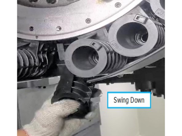
Push the pot back toward the center of the ATC and swing it down.
-
Pull the pot forward to remove it. Note the orientation of the threaded holes in the pins for reassembly.
-
Repeat for every pot.
-
-
-
Remove the center screw on the black center plate that holds the carousel in place.
-
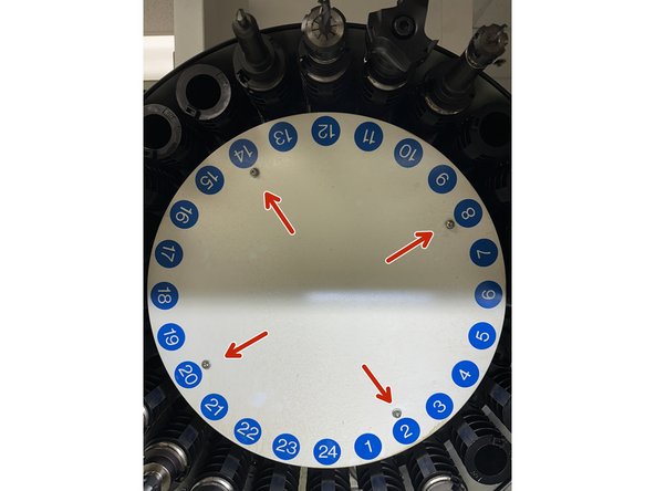
The four outer screws on the center plate are set screws. They do not hold the carousel.
-
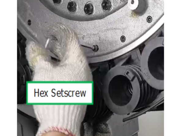
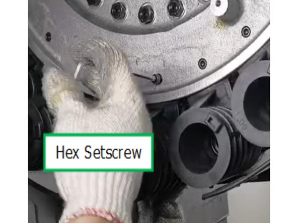
Loosen the four set screws so the disc slides off freely.
-
Slide the carousel disc off. It is light but easily damaged.
-
-
-
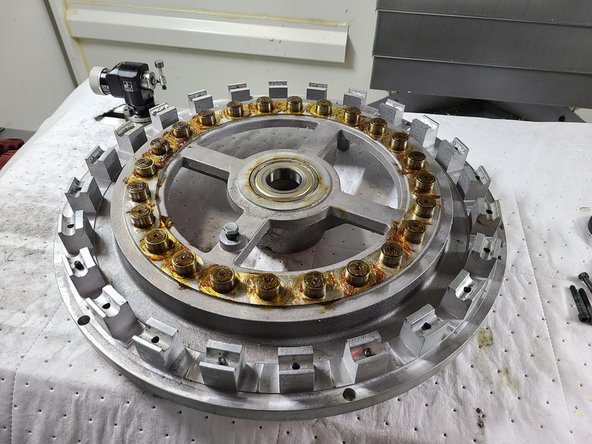
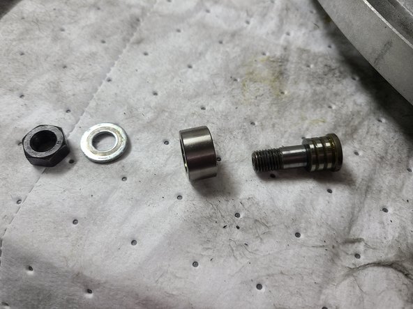
Remove the roller bearings, washers and nuts from the old disc with a 17 mm wrench and a 4 mm hex key.
-
Inspect the bearings for wear. Replace any that are worn.
-
Install the bearings, washers and nuts on the new disc in the same orientation.
-
Hold the stud with the 4 mm hex key and tighten the nut to 35 in-lb.
-
Do not exceed 120 in-lb. Over-torquing can break the bearing stud.
-
Grease the bearings with Mobilith SHC 100.
-
Move the home marker (the steel target on the back of the disc) from the old disc to the same position on the new disc.
-
-
-
First mount: install the disc with T1 one position away from the tool change position. This keeps the home marker clear of the home switch while you check it.
-
Slide the new disc onto the machine with the segmentation cam and bearings aligned.
-
Secure the disc with the center screw.
-
Check that the home marker clears the home switch. If it touches, loosen the switch, set a 2.0 to 2.25 mm gap, and retighten the switch. See Step 8.
-
Tighten the four outer set screws so the center plate is stable. Do not over-tighten; they are for fine adjustment.
-
-
-
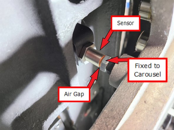
The Home Position Sensor is mounted at a fixed position on the base and triggers when aligned with the steel target on the back of the carousel.
-
Illustration: close-up of the Home Position Sensor at the home position on the carousel.
-
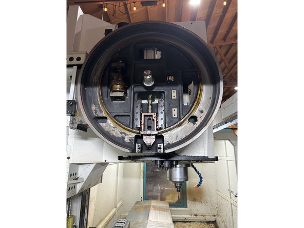
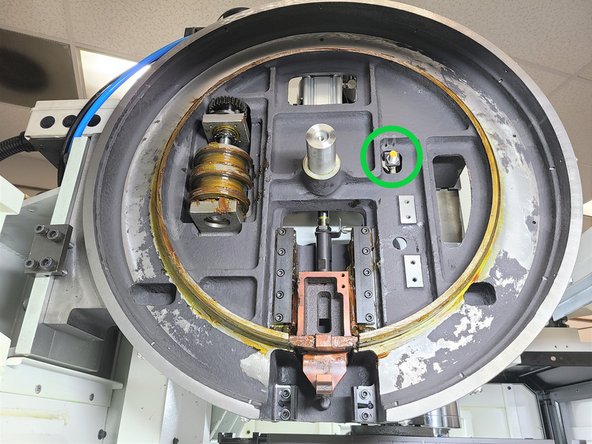
Photo: switch location with the carousel removed. The Home Position Sensor is mounted on the base at about the 2:00 position.
-
Air gap: 2.0 to 2.25 mm (0.080 to 0.090 in).
-
-
-
Slide each pot onto its bracket with the spacer and bracket aligned.
-
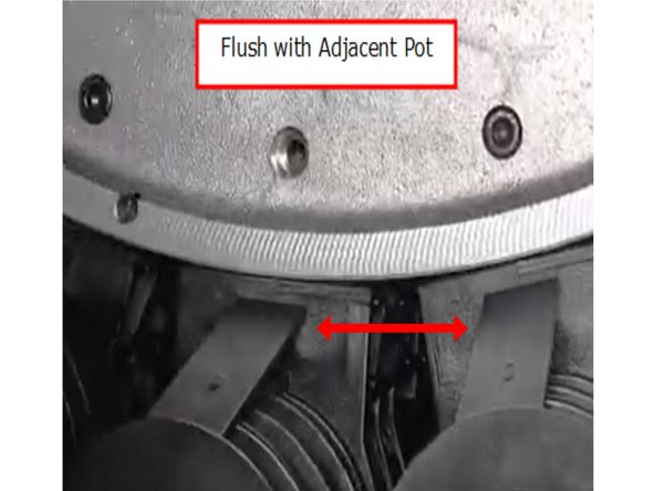
Swing the pot up and pull it forward until it is flush with its neighbors and touching the carousel interior.
-
Pots can be installed the wrong way. Check the right and wrong orientations in VMCsi ATC Pot Replacement.
-
If a pin is hard to start, adjust its threads with a small screwdriver.
-
Apply a small amount of Loctite Blue 242 to the 6 mm socket head cap screw and secure the pot.
-
-
-
Reinstall the carousel cover in its original orientation.
-
Reinstall the gearbox cover and secure it with its seven hex socket screws.
-
Reinstall the ATC outer cover and secure it with the 11 hex socket screws.
-
-
-
Home the ATC.
-
Rotate the carousel and run manual tool changes. Operation should be smooth.
-
Run a full CNC tool change sequence.
-
If the carousel does not home, check the home switch gap. See Step 8.
-



Attached Documents

Team