-
-
This video shows the tool changer going through the process.
-
The VMCsi ATC consists of a vertical carousel consisting of 24 pots, each of which can send a tool to the arm when the pot in the bottom position is lowered vertically. The ATC arm is able to secure a tool holder on each end in order to remove a tool from the spindle while loading a new tool from the lowered pot on the ATC carousel.
-
This makes for faster, more efficient tool changes which require the controller to record the dynamic locations for every tool in the controller’s tool table as their location changes. Tools can be “locked” into the same position on the carousel, or empty spots can be reserved for oversized tooling.
-
-
-
Tool Change Instructions:
-
Select Machine mode and TSM window.
-
Make sure tool window (blue) is highlighted. If not, press the blue highlighted tool window,
-
Press select tool in top of right VSK, pick from tool list and touch the tool you want to load. Press "OK" on right VSK.
-
Press "Cycle Start" on pendant. (as shown on video)
-
At the end of the video, operator points to upper right corner of display that shows the new tool in spindle.
-
-
-
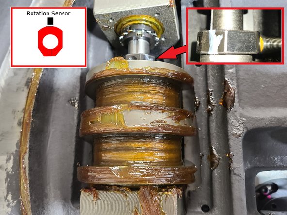
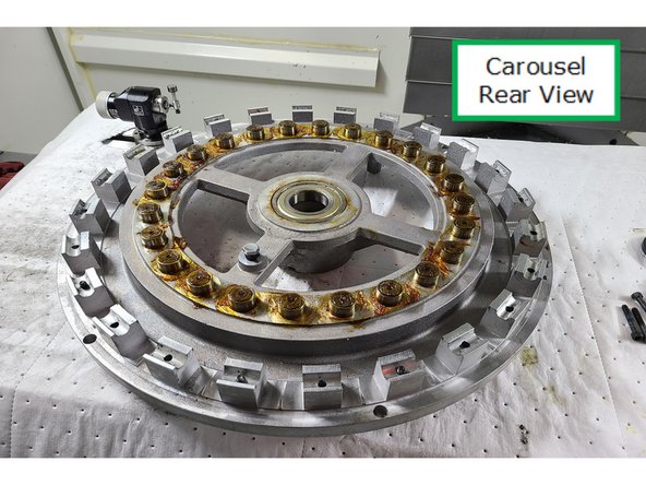
The carousel is not rotated with the same moon gear as our standard ATC. The arm style ATC rotates vertically by use of bearings sticking out the back of the carousel disc. At least 2 and up to 3 of these bearings are in contact with the Segmentation Cam at a time. This Segmentation Cam looks like a helical worm gear, however it is not helical.
-
The Segmentation Cam combines both positioning and rotation. When the Segmentation Cam is rotated by the electric motor, the helical portions act as “ramps” push or pull on the bearings, rotating the disc. When rotation is completed, it transitions to the flat section, and this holds the disc in the correct position for tool changes.
-
Even if off slightly, the pots are ramped into location when lowered, correcting for small misalignment. The Segmentation Cam and bearing need to be kept well-greased.
-
-
-
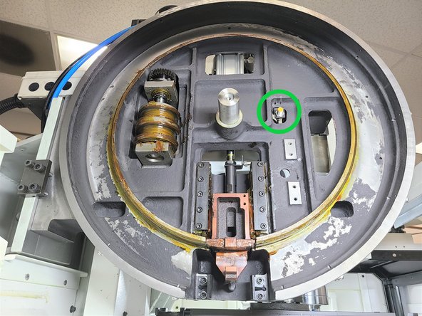
The Segmentation Cam has a nut above it that has a special profile. It has 5 flats and a rounded half. This activates the Proximity Sensor that determines if carousel has rotated one tool position.
-
The Proximity Sensor is magnetic and turns on when the segmentation cam completes a full revolution. The carousel disc bearings ride in the slots on the segmentation cam. One rotation of the segmentation cam results in one tool position change
-
See the upper right inset from the photo which shows the Proximity Sensor activated on the segmentation cam nut. The system monitors this sensor to count carousel rotation to position the correct pot at the bottom of carousel.
-
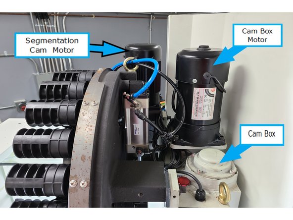
Equipment operating the ATC behind the carousel.
-
The design of the cam prevents Proximity Sensor activation until the carousel movement completes a cycle.
-
Carousel disk rear bearings 142817
-
-
-
Here is the cam nut cycling for one tool change while activating the Proximity Sensor.
-
-
-
Here is an animation of the relation between the Segmentation Cam and the Cams as they cycle through a tool change.
-
-
-
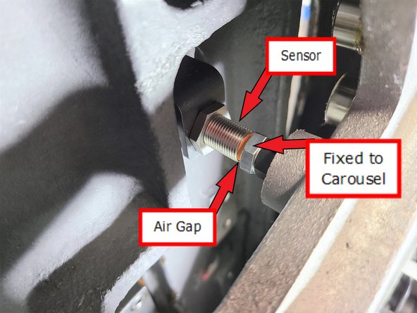
The Home Position Sensor is mounted at a fixed position on the base and triggers when aligned with the steel target on the back of the carousel.
-
Illustration shows a close up of the Home Position Sensor at the home position on the carousel.
-
Photo shows switch location with the carousel removed. The Home Position Sensor Is mounted on the base at about the 2:00 position.
-
Air gap should be .080 - .090" or 2 - 2.25 mm.
-
-
-
The Pots are lifted and lowered via an air cylinder. It is mounted by one bolt on a pivot at the top, and the shaft is threaded. The air cylinder has flow controls to control the lift and lower Pot speed. If the cylinder actuates too quickly, the tools can be flung out of the pot.
-
The air cylinder slides a block in a T slot, pulling or pushing on the freely rotating plastic block on the Pot. When lowering, there is a large metal screw used as a bump stop. The screw is adjustable.
-
The Pots are durable molded parts that are easy to change if needed. Their installation and alignment is simple. Access is easy to all Pots and the carousel by removal of the cover.
-
-
-
The Pots are durable molded parts that are easy to change if needed. Their installation and alignment is simple. Access is easy to all Pots and the carousel by removal of the cover.
-
The air cylinder slides a block in a T slot, pulling or pushing on the freely rotating plastic block on the Pot. When lowering, there is a large metal screw used as a bump stop. The screw is adjustable.
-
-
-
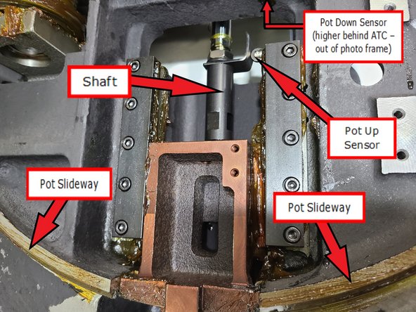
The shaft pulls up the piston which in turn swings the Pot connected to it down ready to exchange tools. When the Pot is fully down and ready to exchange tools, the Pot Down sensor is activated. The Pot Down sensor is located behind the base and out of sight. It is also several inches higher than the top of the photo.
-
Pots are lowered to release a tool to the arm and then lift back up with the new tool. The Pot Up and Pot Down sensors tell the controller when a specific pot has finished its travel and that the arm can begin movement. Photo shows the ATC with all the pots removed as well as the carousel disc to show tool changer operations.
-
The Pot slideway path is where the Pots line up around the circumference of the base. The photo shows the Pot Up Sensor touching its bracket. This means that the bottom Pot below the piston (in tool change position) is in the up position. The carousel can now be allowed to rotate.
-
When tools are exchanged, the shaft pushes the piston down moving the Pot back up triggering the Pot Up Sensor when in position.
-
-
-
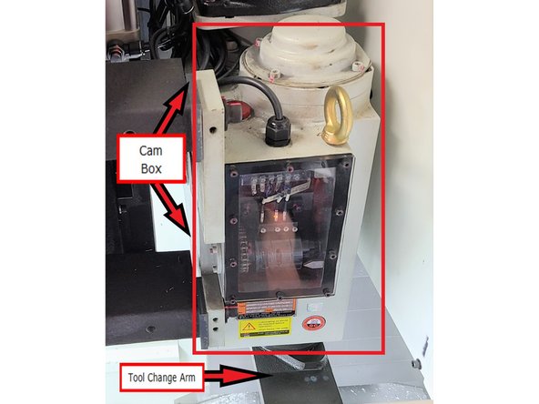
The Cam Box is a complex piece of equipment and it is preferred to avoid touching them except for routine maintenance. There are a few sensors that note the position, but the internal workings of the Cam Box are intricate.
-
It is possible that the sensors could become damaged, but this has not been suggested as likely or common.
-
This component may need to be replaced instead of repaired. The motor itself can be replaced easily, but the internal components are complex and likely require a good bit of work to disassemble, diagnose, rebuild, etc.
-
-
-
The Cam Box converts pure rotational motion from the cam box motor into ATC arm partial rotation, lowering, full rotation, lifting, full rotation, and partial counter rotation.
-
-
-
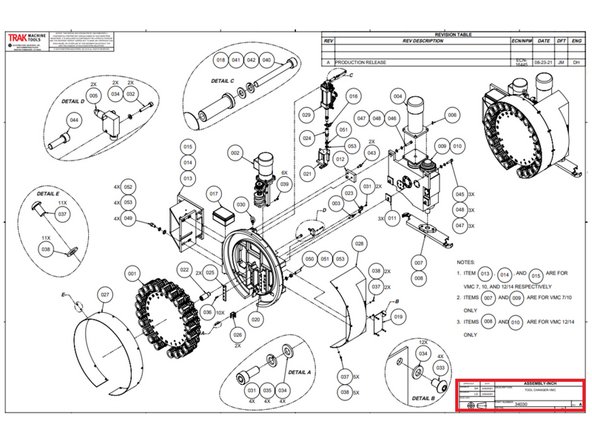
Drawings and parts lists are available on the company computer system:
-
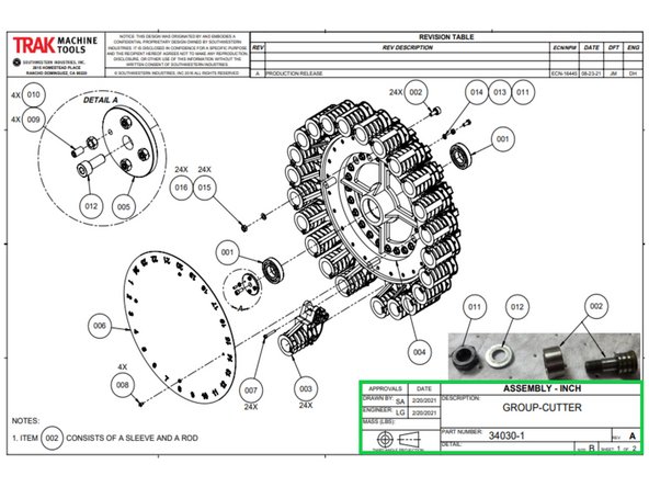
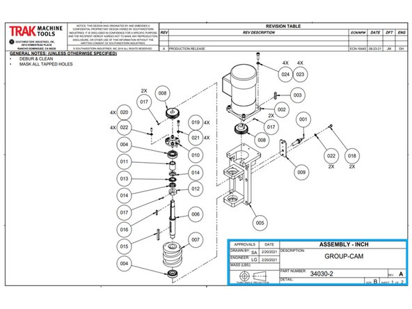
34030 - Complete ATC Details
-
34030-1 - Carousel & Pot Details
-
34030-2 - ATC Motor Details
-
Cancel: I did not complete this guide.
One other person completed this guide.

