
-
-
The method for entering Spindle Service Mode depends on whether the machine is using the Old PLC or New PLC.
-
Press [Diagnostics] → [Version]
-
Locate the PLC User Program line.
-
03.xx.xx → Old PLC
-
05.xx.xx or higher → New PLC
-
-
-
This step applies only to machines using the New PLC (05.xx.xx or higher).
-
Verify the E-Stop is disengaged.
-
Press [Reset]
-
While holding [Spindle Stop], press [Feed Stop] three (3) times.
-
Confirm [Feed Stop] begins blinking slowly.
-
-
-
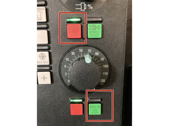
This step applies only to machines using the Old PLC (03.xx.xx).
-
Verify the E-Stop is disengaged.
-
Press [Reset]
-
Press and hold [Spindle Stop]
-
While holding [Spindle Stop], press [Feed Start] three (3) times.
-
Confirm [Feed Start] begins blinking slowly.
-
-
-
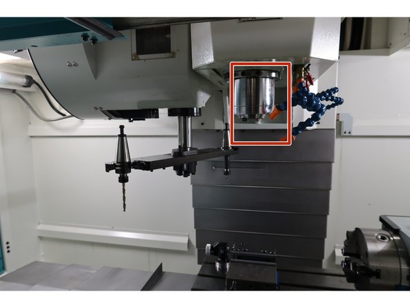
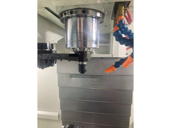
The recovery procedure depends on whether a tool is currently captured by the spindle.
-
Inspect the spindle area and ATC arm to determine which condition applies:
-
Fault with spindle empty
-
Fault with tool in spindle.
-
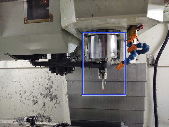
Treat the fault as “Tool in Spindle” if:
-
The tool is aligned with the spindle and
-
The tool is partially or mostly inserted into the spindle
-
If the drawbar fingers are capturing the retention knob, the tool is considered in the spindle, even if it is not fully seated.
-
-
-
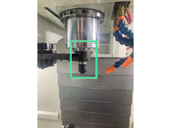
If a tool is in the spindle, do not attempt to remove it using this step.
-
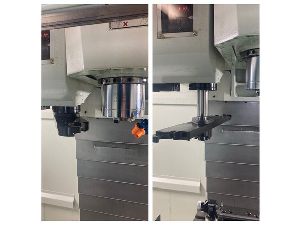
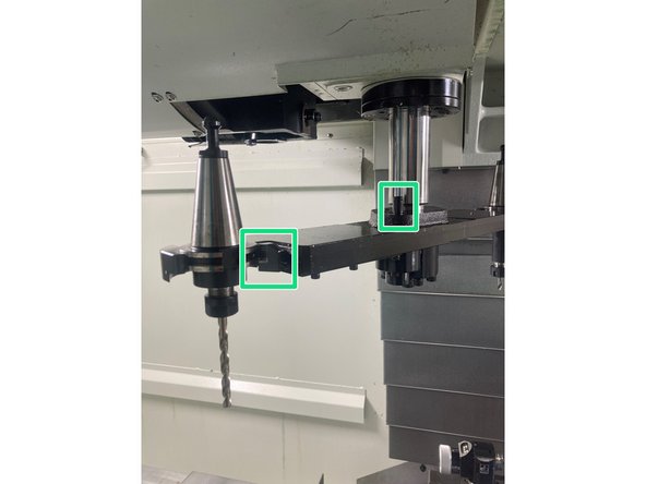
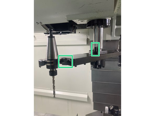
Identify the ATC arm position:
-
Up position (left image) — the gripper can be pressed directly.
-
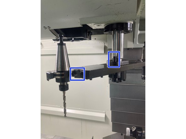
Down position (right image) — the release pin on the arm must be pressed before the gripper will open.
-
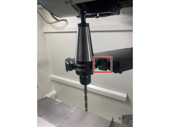
Remove the tool(s) from the ATC arm by pressing the gripper and pulling the tool straight out.
-
If the arm is in the down position, the circled pin on the arm must be pressed down before the gripper can be depressed.
-
If no tool is in the spindle, both tools may be removed using this method.
-
-
-
Verify the machine is in Spindle Service Mode.
-
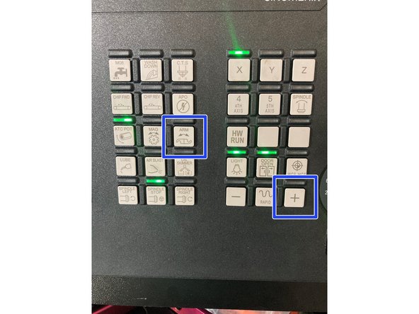
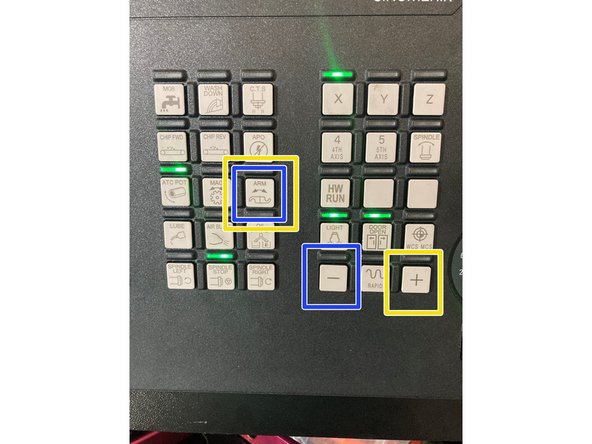
Press and hold [Arm], then tap [+] to move the ATC arm to the home position.
-
Once the arm is at home, press and hold [Pot], then tap [-] to return the pot to the Up position.
-
If the arm returns home with no tools installed, proceed to Step 15 — Confirming Spindle Home.
-
-
-
Before moving the ATC arm, determine when the fault occurred:
-
Fault during tool insertion into the spindle
-
Fault during tool removal from the spindle
-
Choose the correct recovery direction:
-
Insertion fault → Move the arm backward [−] to back the tool out.
-
Removal fault → Move the arm forward [+] to complete the removal.
-
Proceed to the appropriate recovery step based on this condition.
-
Moving the arm in the wrong direction increases the risk of dropping the tool or damaging the ATC.
-
-
-
This video shows the tool insertion sequence into the spindle.
-
If the control faulted during tool insertion, proceed to Step 9 — Removing Tool (Insertion Phase).
-
If the control did not fault during insertion, proceed to Step 10 — Removing Tool (Removal Phase).
-
-
-
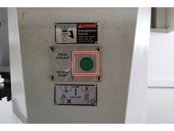
Place cardboard or rags on the table to protect the machine if the tool drops.
-
This procedure requires two people, one holding the green Manual Tool Change button and one operating the ATC controls.
-
The green button must remain pressed until the tool is completely clear of the spindle.
-
Verify the machine is in Spindle Service Mode.
-
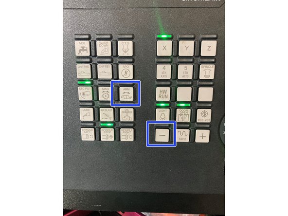
Press and hold [Arm], then tap [−] to move the arm back toward Home.
-
Using [Arm] & [−] reverses the insertion motion and reduces the risk of dropping the tool.
-
Once clear of the spindle, remove the tool using the gripper (press the release pin first if the arm is down).
-
Press and hold [Pot], then tap [−] to return the pot to the Up position, then proceed to Step 15.
-
-
-
This video shows the tool removal sequence from the spindle.
-
If the control faulted during tool removal, proceed to Step 11 — Returning the Arm to Home (Tool in Spindle).
-
-
-
Place cardboard or rags on the table to protect the machine if the tool drops.
-
This procedure requires two people, one holding the green Manual Tool Change button and one operating the ATC controls.
-
The green button must remain pressed until the tool is completely clear of the spindle.
-
Verify the machine is in Spindle Service Mode.
-
Press and hold [Arm], then tap [+] to move the arm forward toward Home.
-
Using [Arm] & [+] advances the tool removal motion and reduces the risk of dropping the tool.
-
Once clear of the spindle, remove the tool using the gripper (press the release pin first if the arm is down).
-
Press and hold [Pot], then tap [−] to return the pot to the Up position.
-
-
-
After the spindle-side tool has been addressed, verify the tool is not still captured in the ATC pot.
-
If a tool remains in the pot, press and hold [Pot], then tap [−].
-
Verify the pot returns to the Up position and clears the arm travel path.
-
-
-
Move the ATC arm to a safe position using [Arm] with [+] or [−].
-
Determine when the fault occurred:
-
Fault during insertion into the pot
-
Fault during removal from the pot
-
Select the correct direction:
-
Insertion fault → Press [Arm] & [−] to back the tool out of the pot.
-
Removal fault → Press [Arm] & [+] to advance the tool out of the pot.
-
If the arm is in the down position, press the release pin to open the gripper to remove tool.
-
-
-
Video of ATC Return to home using [Arm] & [+]
-
-
-
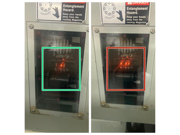
Look through the front ATC window to view the ATC LEDs.
-
When ARM returns to home position, only LED in the middle should be active.
-
When multiple lights (or any single light other than the center one) are lit, the ARM is not at the home position.
-
-
-
Press [Reset] to exit Spindle Service Mode.
-
Press [Jog] and [Ref Point] on the MCP and confirm both indicator lights are on.
-
Press [Mag] & [+] together to reference the magazine.
-
Verify Pot 1 is in the tool change position.
-
Verify the green arrow in the first column of the tool table points to Tool 1.
-
Reinstall any tools that were manually removed during the clearing process.
-
Verify the tools in the magazine match the tool table.
-
ATC fault clearing is complete.
-

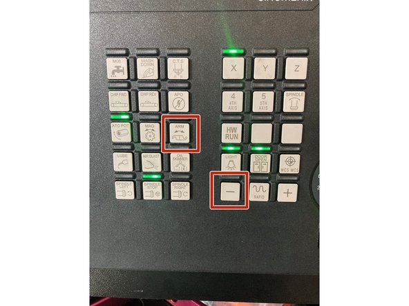
![Press and hold [Arm], then tap [+] to move the ATC arm to the home position.](https://d3t0tbmlie281e.cloudfront.net/igi/trakmtsupport/PAuERl4DMGhpAR6S.medium)


![Move the ATC arm to a safe position using [Arm] with [+] or [−].](https://d3t0tbmlie281e.cloudfront.net/igi/trakmtsupport/4aoRPiZ15GTBduL2.medium)
![Press [Reset] to exit Spindle Service Mode.](https://d3t0tbmlie281e.cloudfront.net/igi/trakmtsupport/LMUbKIMRAyJyecNd.medium)
![Press [Jog] and [Ref Point] on the MCP and confirm both indicator lights are on.](https://d3t0tbmlie281e.cloudfront.net/igi/trakmtsupport/Jl1VYOFk1iqA4bIr.medium)