Introduction
The OTS tool setting probe (P/N 34080-2) measures tool length and diameter on the table. This guide assembles the OTS, initializes the batteries, sets the probe configuration, and mounts and aligns it on the table.
The OMI-2T receiver (P/N 34080-10) must already be installed: VMCsi Probe Tool and Probe Part Options - Mount Probe Receiver.
This is the tool probe. For the OMP40-2 spindle probe (P/N 34080-1), see VMCsi Probe Part Option - Set Up Spindle Probe.
The 34050 assembly drawing and the Renishaw OTS manual are attached at the end of this guide.
Tools
Parts
No parts specified.
-
-
Insert the break stem through the captive link, then install both onto the OTS body (first image).
-
Tighten the break stem with a 5 mm Allen wrench. Torque to 1.84 to 1.99 lbf-ft.
-
Bend the captive link upward.
-
Install the stylus onto the coupler. Tighten set screw #1 (top, stylus) with a 2 mm Allen wrench. Torque to 0.74 to 0.89 lbf-ft.
-
Insert the cap screw through the bent captive link and secure it to the bottom of the coupler with the support bar and a 3 mm Allen wrench. Torque to 1.84 to 1.99 lbf-ft.
-
Tighten set screw #2 (bottom, cap screw) with the support bar and a 2 mm Allen wrench (second image). Torque to 0.74 to 0.89 lbf-ft.
-
Hold the support bar in place to counter twisting, so the break stem is not over-stressed.
-
-
-
Twist off the battery cover and remove the batteries.
-
Wait about 5 seconds, reinstall the batteries, and twist the cover back on.
-
Keep coolant and debris out of the battery compartment.
-
The LEDs flash red, green, blue. At this sequence, deflect and hold the stylus right away to enter configuration mode. Keep holding it into Step 3.
-
Do not remove the batteries while in configuration mode. To exit, leave the stylus untouched for more than 20 seconds.
-
The probe then flashes battery status:
-
5 red flashes: batteries good.
-
Red and blue repeating: batteries low, replace them.
-
-
-
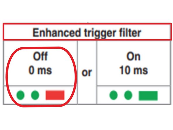
With the stylus still deflected, the enhanced trigger filter menu appears. Release the stylus.
-
Two green flashes, then a long red flash, show the trigger filter setting.
-
Confirm the enhanced trigger filter is Off (0 ms), then deflect and hold the stylus 4+ seconds to move to the next menu.
-
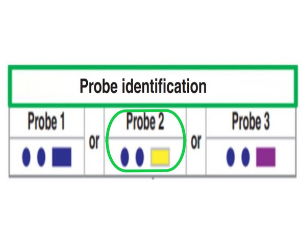
Probe identification: the LEDs flash blue, blue, yellow. If a different sequence shows, deflect and release (about 1 second) to cycle through the settings.
-
When blue, blue, yellow shows, deflect and hold 4+ seconds to accept.
-
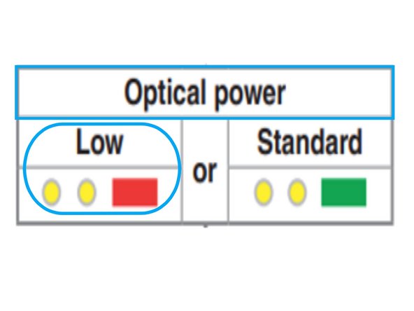
Optical power: deflect and release until you see two yellow flashes, then a long red flash.
-
Leave the stylus untouched for more than 20 seconds to save the settings.
-
-
-
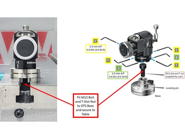
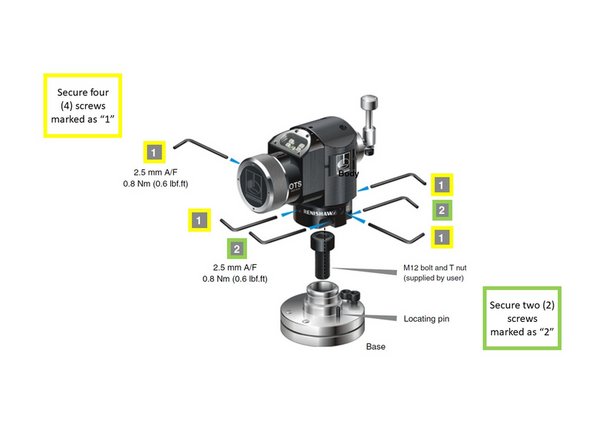
Loosen the four screws labeled "1" with a 2.5 mm Allen wrench to separate the OTS body from the base (first image).
-
Loosen the two screws labeled "2" so the base mounts freely.
-
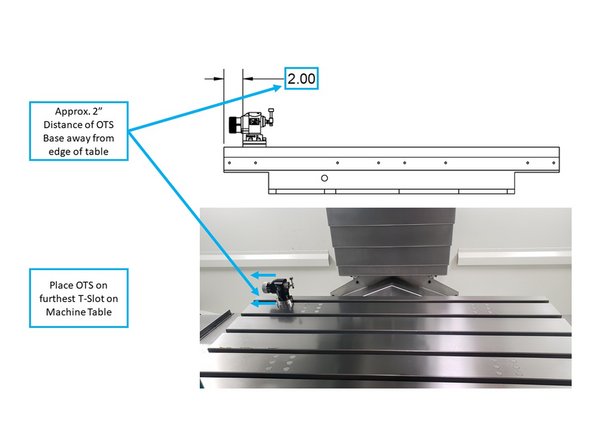
Secure the OTS base to the table with the M12 bolt and T-slot nut.
-
Use the furthest T-slot, about 2 in from the left edge of the table, clear of any collision path (second image).
-
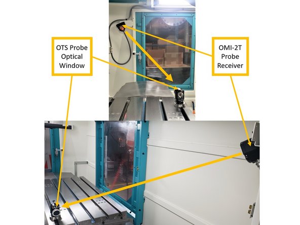
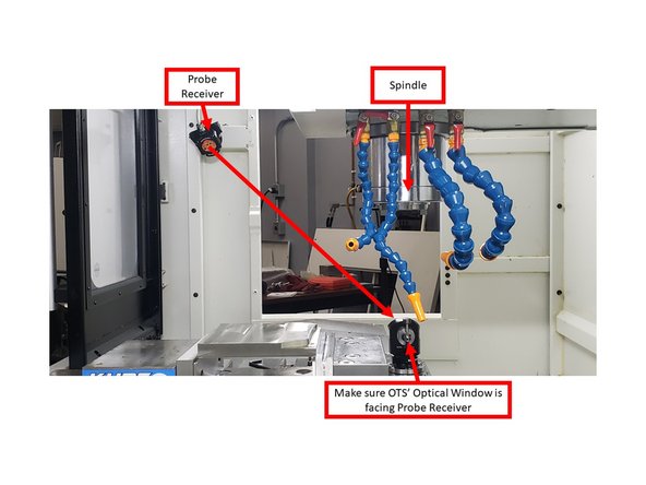
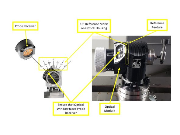
Point the OTS optical window toward the OMI-2T receiver.
-
-
-
Reinstall the body on the base and tighten the four screws labeled "1". Torque to 0.6 lbf-ft.
-
Tighten the two screws labeled "2". Torque to 0.6 lbf-ft.
-
-
-
The optical module has seven positions, 15° apart.
-
Jog the table until the OTS is directly under the spindle. This is the tool touch-off position, and it must be in line of sight of the receiver.
-
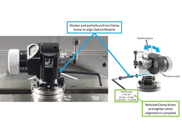
Slacken the clamp screw with a 4 mm Allen wrench and partly remove it.
-
Rotate the optical module, lining up a 15° mark on the housing with the reference feature on the body.
-
Keep rotating until the optical window lines up as closely as possible with the receiver.
-
Reinstall the clamp screw and torque it to 3.7 lbf-ft.
-
-
-
Level the stylus and calibrate the OTS before use.
-
-


Attached Documents

Team