Introduction
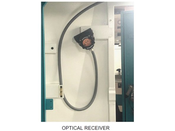
Mount and wire the OMI-2T probe receiver (P/N 34080-10) on any VMCsi. The receiver is required for both the Probe Part option (OMP40-2 spindle probe, P/N 34080-1) and the Probe Tool option (OTS tool setting probe, P/N 34080-2).
Parts used: receiver bracket (P/N 34080-4), 24VDC power cable (P/N 31594-2), probe jumper wire (P/N 34080-9), cable fitting with seal (P/N 34080-6), terminal block connector (P/N 50776-4), and the 3D printed jig (P/N 34050-JIG).
The 34050 assembly drawing and the Renishaw OMI-2T installation guide are attached at the end of this guide.
-
-
Turn off and lock out main power before working in the electrical cabinet or the PPU.
-
-
-
Tap these M6 holes:
-
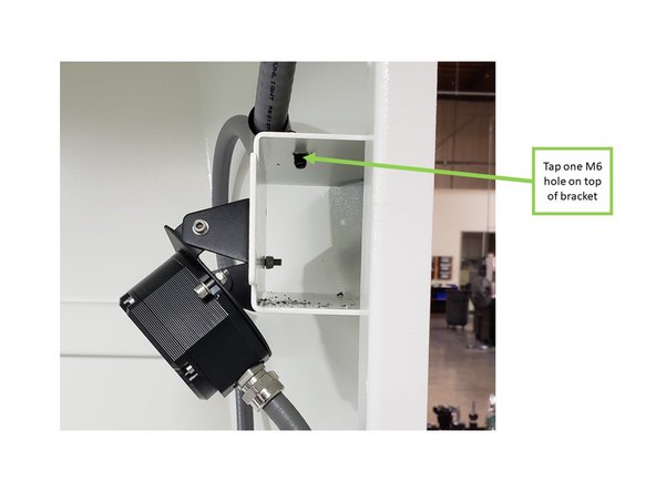
Tap one M6 hole on top of the bracket next to the left-side door, from inside the machine.
-
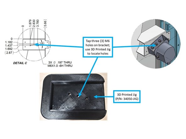
Tap three M6 holes on the front face of the same bracket, as shown in the image. The OMI-2T will mount here.
-
Use the 3D Printed Jig (P/N 34050-JIG) to locate the three mounting holes on the bracket.
-
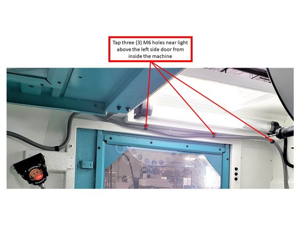
Tap three M6 holes near the light above the left-side door, from inside the machine.
-
Some machines may come with these holes pre-tapped.
-
-
-
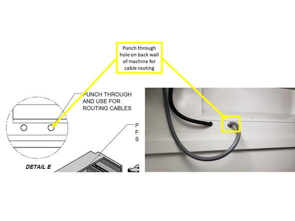
Punch a through-hole in the back wall of the machine for cable routing (see image).
-
VMC7si and VMC10si: the hole is near the bracket in the top left corner of the back wall.
-
VMC12si and VMC14si: the hole is at the very top left corner of the back wall, where there is no bracket.
-
-
-
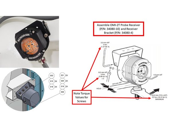
Fasten the OMI-2T receiver assembly to the receiver bracket (P/N 34080-4) with two M5 screws, washers and nylon lock nuts (supplied by Renishaw).
-
Torque to 3.68 lbf-ft.
-
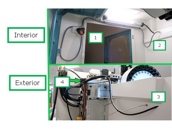
Route the cables from the receiver mount (1) along the left interior wall to the rear wall (2), exiting out the back.
-
Continue routing the cables from the exterior rear (3) into the cable channel (4) leading to the electrical cabinet.
-
Mount the OMI-2T Receiver and Bracket to the machine using three M6 screws (P/N M6 12 27B) and serrated washers (P/N 24009-3).
-
Fasten to the three M6 tapped holes previously added to the interior bracket.
-
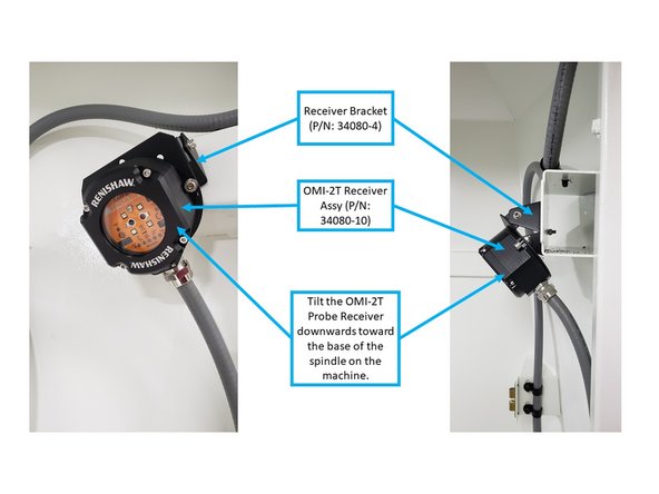
Tilt the receiver downward toward the base of the spindle.
-
Orient the receiver as shown in the image to keep coolant out of the core openings.
-
-
-
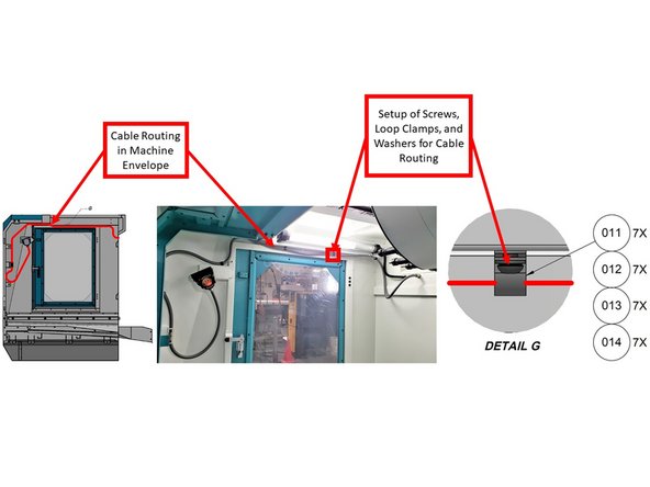
Refer to the first image for proper cable routing and the correct placement of loop clamps, screws, and washers.
-
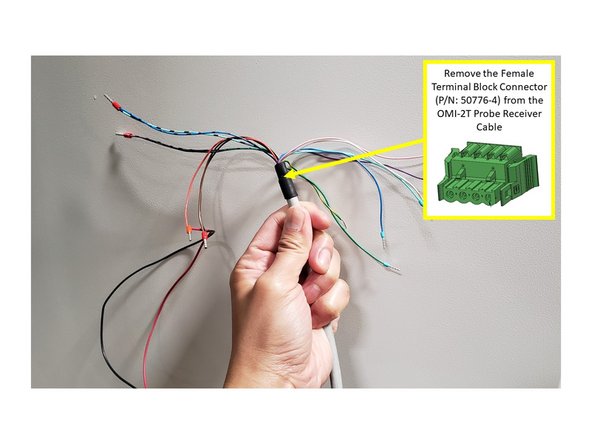
Before routing the cable, remove the Female Terminal Block Connector (P/N 50776-4) from the end of the OMI-2T cable, and tape the wires together to help the cable pass through the knockout hole and machine cable troughs.
-
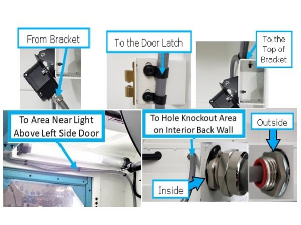
After the OMI-2T is mounted near the left-side door, route the cable to the front door latch from inside the machine.
-
Remove the two screws from the door latch, attach two loop clamps to hold the cable in place, and reinstall the screws.
-
Route the cable from the door latch back to the top of the bracket where the OMI-2T is installed. Use one M6-1.0x10 (27B) screw, one washer, and one loop clamp to secure it.
-
Continue routing the cable up to the three tapped M6 holes near the light above the left-side door. Use three M6-1.0x10 (27B) screws, three washers, and three loop clamps.
-
Guide the cable through the knockout hole on the back interior wall of the machine.
-
Install the fitting with seal (P/N 34080-6) when routing the cable through this hole. Refer to the inset images for proper assembly.
-
-
-
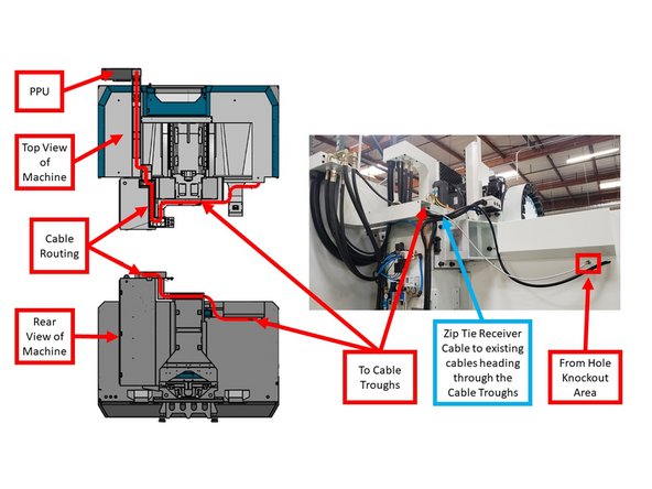
From the knockout hole, zip tie the OMI-2T cable to existing cables leading toward the cable troughs.
-
Route the cable through the cable troughs from the back of the machine to the PPU.
-
Follow the existing cable paths inside the enclosed cable troughs for a clean and secure installation.
-
-
-
Remove the tape from the colored wires on the OMI-2T Probe Receiver cable.
-
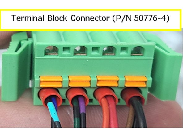
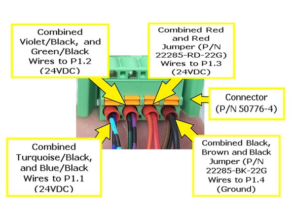
Reconnect the wires to the Female Terminal Block Connector (P/N 50776-4) as shown in the image.
-
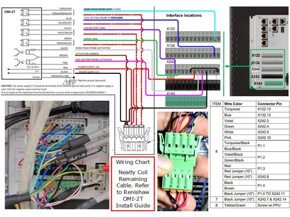
Install the Turquoise/Black and Blue/Black wires into Position 1 (P1.1).
-
Install the Violet/Black and Green/Black wires into Position 2 (P1.2).
-
Install the Red and Red Jumper Wires (P/N 22285-RD-22G) into Position 3 (P1.3).
-
Install the Black, Brown, and Black Jumper Wires (P/N 22285-BK-22G) into Position 4 (P1.4).
-
-
-
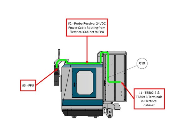
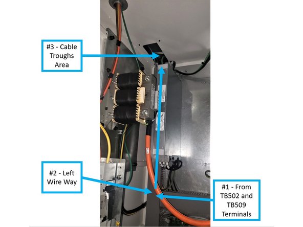
Route the Probe Receiver 24VDC Power Cable (P/N 31594-2) from the electrical cabinet to the PPU using the cable troughs.
-
Refer to the first image on the left (with the green line) for the recommended cable path.
-
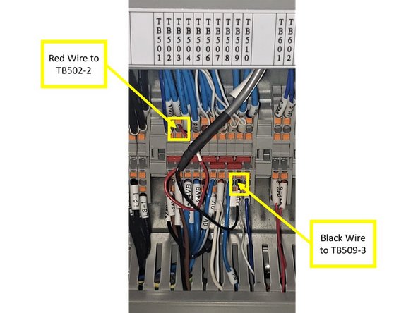
Connect the Red wire (24VDC) to TB502-2.
-
Connect the Black wire (Ground) to TB509-3.
-
From terminals TB502 and TB509, guide the cable through the left wireway and into the cable troughs toward the PPU.
-
-
-
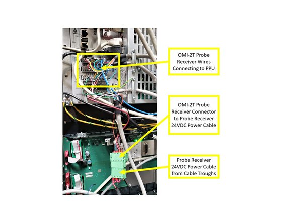
From the cable troughs, connect the Probe Receiver 24VDC Power Cable to the OMI-2T Receiver Assembly Cable.
-
Neatly coil and store both cables inside the pendant housing.
-
The OMI-2T Receiver Cable must connect to both the Power Cable and the PPU.
-
Refer to the second image on the left for the Wiring Interconnections Chart, which shows how to connect the OMI-2T Receiver Cable to the PPU and Power Cable.
-
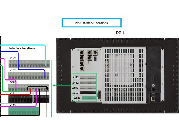
Refer to the third image on the left for the PPU Interface Terminal Block designations.
-
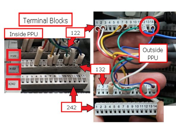
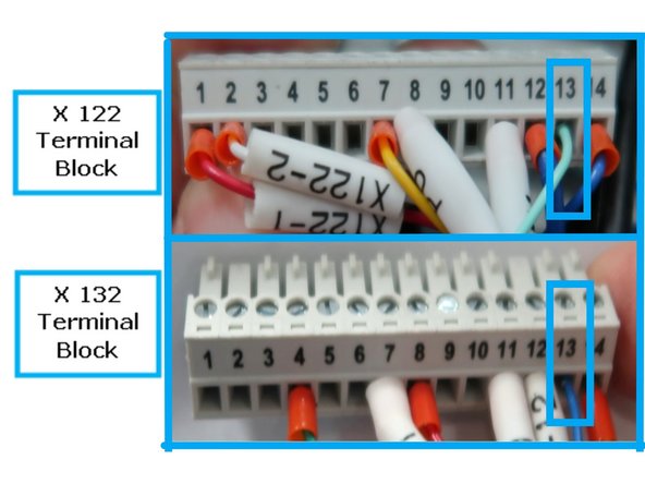
Terminal blocks X122, X132, X242, and X252 each have 14 terminals. X143 has 12 terminals.
-
Each terminal block can be removed and reinstalled to simplify the wiring process.
-
-
-
Connect the OMI-2T Receiver Cable to terminal blocks X122, X132, and X242 in the PPU.
-
Positions X122.13 and X132.13 are empty as shipped; the receiver wires go there (circled in the image).
-
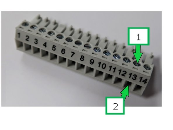
To install a wire:
-
Loosen the terminal screw.
-
Insert the wire into the terminal.
-
Retighten the screw to secure the connection.
-
-
-
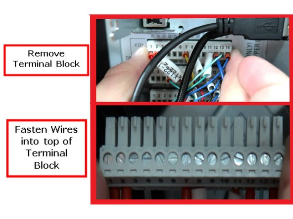
You may need to remove the terminal blocks from the PPU to install the wires properly.
-
To remove a terminal block, do not squeeze the ends. Hold the ends firmly and pull while gently wiggling it free. There are no retainer clips, just a tight fit.
-
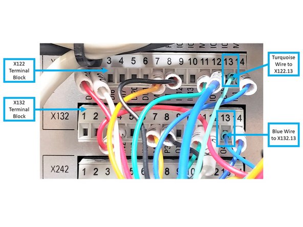
Refer to the images showing the terminal blocks installed in the PPU and the specific wiring positions.
-
The second image is a close-up of the wire locations.
-
On Terminal Block X122, install the Turquoise wire from the OMI-2T Receiver Cable to X122.13.
-
On Terminal Block X132, install the Blue wire to X132.13.
-
-
-
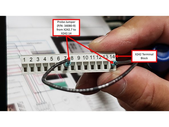
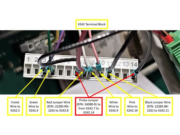
On Terminal Block X242, install the Probe Jumper Wire (P/N 34080-9) between X242.7 and X242.14.
-
Connect the Violet wire to X242.3 and the Green wire to X242.4.
-
Connect the White wire to X242.9 and the Pink wire to X242.10.
-
Route the Red Jumper Wire (P/N 22285-RD-22G) from Position 3 of the OMI-2T Receiver Terminal Block Connector to X242.8.
-
Route the Black Jumper Wire (P/N 22285-BK-22G) from Position 4 of the same connector to X242.11.
-
Reinstall all terminal blocks into the PPU.
-
-
-
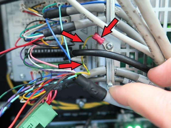
Install the Green/Yellow wire to the machine ground using a Torx T10 screw, as shown in the image.
-
-
-
Set up each probe option installed on this machine:
-
Probe Part option, OMP40-2 spindle probe (P/N 34080-1): VMCsi Probe Part Option - Set Up Spindle Probe
-
Probe Tool option, OTS tool setting probe (P/N 34080-2): VMCsi Probe Tool Option - Set Up Tool Setting Probe
-
Attached Documents

Team