Introduction
The OMP40-2 spindle probe (P/N 34080-1) sets part zeros, applies work offsets, and checks part geometry. This guide assembles the probe, initializes the battery, sets the probe configuration and adds it to the tool list.
Parts: stylus (P/N 34080-5), CAT40 shank (P/N 34080-8), retention knob (P/N 26800-2).
The OMI-2T receiver (P/N 34080-10) must already be installed: VMCsi Probe Tool and Probe Part Options - Mount Probe Receiver.
This is the part probe. For the OTS tool setting probe (P/N 34080-2), see VMCsi Probe Tool Option - Set Up Tool Setting Probe.
The 34050 assembly drawing and the Renishaw OMP40-2 installation guide are attached at the end of this guide.
Tools
Parts
No parts specified.
-
-
Thread the stylus (P/N 34080-5) into the probe with the Renishaw-supplied tool.
-
Torque the stylus to 1.3 to 1.6 lbf-ft.
-
Use only the supplied tool. It flexes before it can over-torque and damage the probe.
-
Insert the probe into the CAT40 shank (P/N 34080-8).
-
Tighten the six shank set screws with a 2 mm Allen wrench: two upper pointed, four lower flat.
-
Torque all six to 0.4 to 1.1 lbf-ft.
-
Install the retention knob (P/N 26800-2) into the CAT40 shank.
-
-
-
Remove the battery cover with a flat head screwdriver.
-
Remove the batteries, wait 5 seconds, reinstall them, and secure the cover.
-
Keep coolant and debris out of the battery compartment.
-
Watch the LED flash red → green → blue.
-
At the blue flash, deflect and hold the stylus to enter configuration mode. Keep holding it into Step 3.
-
Do not remove the batteries while the probe is in configuration mode.
-
To exit configuration mode at any time, leave the stylus untouched for 20 seconds.
-
Battery status: 8 red flashes is good. Red and blue repeating means replace the batteries.
-
-
-
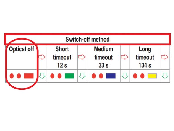
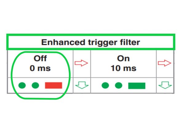
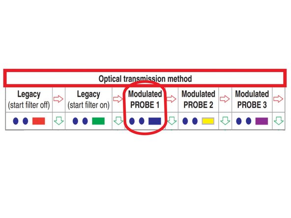
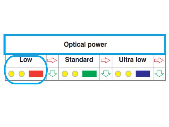
You are still holding the stylus deflected from Step 2. The probe steps through four menus in order: switch-off, trigger filter, transmission, optical power.
-
In every menu:
-
Deflect and release quickly (about 1 second) to step to the next option.
-
Deflect and hold 4+ seconds to accept the option shown and move to the next menu.
-
Switch-off method: Optical off. Menu header: two red flashes, then a long red flash.
-
Enhanced trigger filter: On, 10 ms. Menu header: two green flashes, then a long red flash.
-
Leave the trigger filter on. It keeps machine vibration from causing false triggers, and a false trigger mid-cycle reads as a bad calibration, not a fault.
-
-
-
Optical transmission method: Modulated, PROBE 1. Cycle until the probe flashes blue only, then hold 4+ seconds.
-
Optical power: Low. Cycle until you see two yellow flashes, then a long red flash.
-
Leave the stylus untouched for 20+ seconds to save and exit configuration mode.
-
-
-
Press [JOG] on the MCP.
-
Go to [M] → [Act. values Machine].
-
The axis labels change to MX1, MY1, MZ1. You are reading machine coordinates.
-
Go to [Tool List]. Choose a location outside the ATC range: not 1 to 24 on a 24-tool ATC, not 1 to 40 on a 40-tool ATC.
-
Press [New tool] → select 710 - 3D probe → press [OK].
-
-
-
Length: measure from the stylus tip to the top of the flange with the 8 in caliper, then add 0.25 in. Enter it in [Length].
-
Diameter: measure the ruby, or read it off the packaging. Enter it in [ø].
-
These are seed values. Calibration measures the probe and writes the exact length back to the tool data. The seed only has to be close enough for the first run to be accepted.
-
-
-
Calibrate the probe before use.
-
-




Attached Documents

Team