Introduction
Calibrate the OMP40-2 spindle probe (P/N 34080-1): stylus runout, then length and diameter. To calibrate the OTS tool setting probe (P/N 34080-2), see VMCsi Probe Tool Option - Calibrate Tool Setting Probe.
Two paths, depending on what your shop has:
1-2-3 blocks only: Step 4, then Step 8 onward.
Precision Calibration Tool: Steps 5 to 7, then Step 8 onward.
Both paths end at the same calibration steps.
Tools
Parts
No parts specified.
-
-
The probe must already be set up and in the tool list. VMCsi Probe Part Option - Set Up Spindle Probe
-
On a machine with two spindle probes, set up the data records first. VMCsi Probe Part Option - Set Up Two Spindle Probes
-
You need a dial indicator, a ring gauge and two 1-2-3 blocks, plus the Precision Calibration Tool if your shop has one.
-
Recalibrate after a stylus change or a crash.
-
-
-
Load the OMP40-2 into the spindle.
-
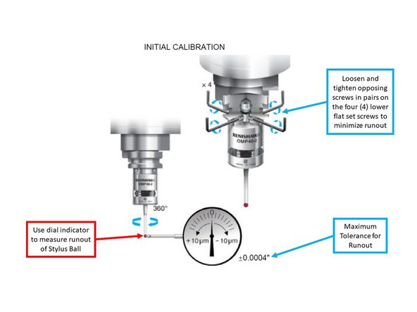
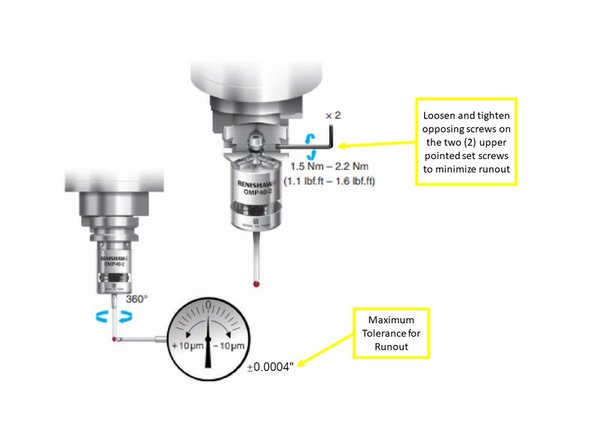
Check runout at the ruby tip with a dial indicator while turning the spindle by hand.
-
First pass: get runout within ±0.0004 in.
-
Adjust the four lower flat set screws in opposing pairs.
-
Fine-tune with the two upper pointed set screws, also in opposition.
-
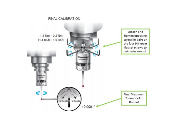
Final pass: reduce runout to ±0.0001 in or better.
-
Re-adjust the lower screws as needed.
-
Finish with the upper screws. Do not calibrate until runout is within ±0.0001 in.
-
-
-
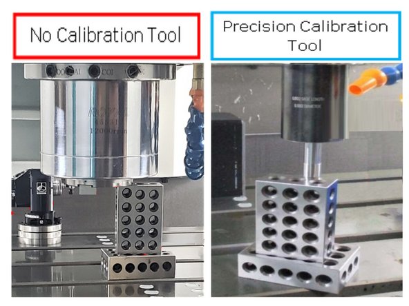
Pick the path for the equipment your shop has. Both paths end at Step 8.
-
No calibration tool (1-2-3 blocks only):
-
Do Step 4, then skip to Step 8.
-
Precision Calibration Tool:
-
Do Steps 5 to 7, then Step 8.
-
-
-
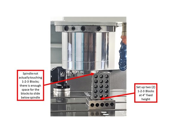
Stack two 1-2-3 blocks to make a 4 in fixed height on the table.
-
Jog the spindle down until the blocks no longer slide underneath it.
-
Jog the spindle up slowly until the blocks just slide freely underneath.
-
The spindle should sit just above the blocks, not touching them.
-
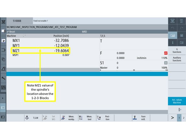
Record the MZ1 value shown at this height.
-
You enter this value in Step 9. Skip to Step 8.
-
-
-
Press [T, S, M].
-
Press [Work offset].
-
Select an available offset, for example G54.
-
Press [CYCLE START] to activate it.
-
Confirm the offset name (for example G54) shows on the screen.
-
Press [Select tool].
-
If the calibration tool is already in the tool list, select it, load it with [CYCLE START], and skip to Step 7.
-
If it is not, continue to Step 6 to add it.
-
-
-
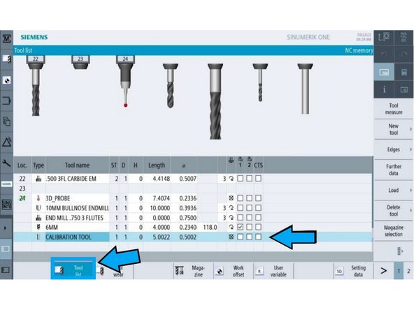
In the New tool - favorites window, press [Spec. tool 700-900].
-
Select 725 - Calibrating tool.
-
Press [OK] to add it to the tool list.
-
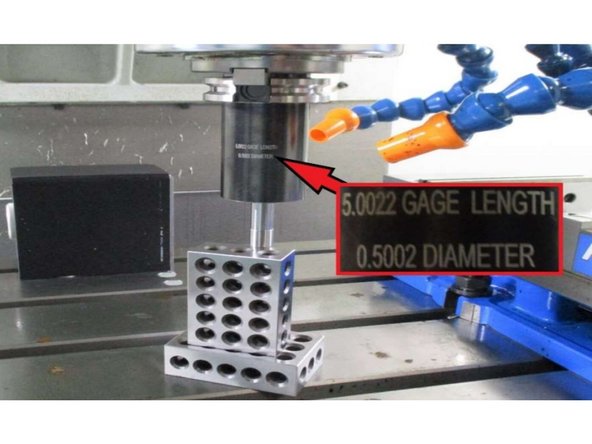
Enter the tool length and diameter engraved on the calibration tool body.
-
Press [JOG] on the MCP.
-
Press [T, S, M], then press [Select tool].
-
Select the calibration tool and press [CYCLE START] to load it.
-
-
-
Stack two 1-2-3 blocks on the table (4 in).
-
Lower the calibration tool below the top of the blocks, beside them.
-
Raise the tool slowly until the blocks just slide underneath without contact.
-
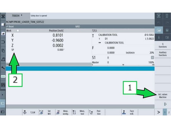
Press [Act. values Machine] to turn off machine values. The display switches to work offset values.
-
Press [Z=0].
-
Confirm Z reads 0.
-
-
-
Press [T, S, M].
-
Click the T field, then press [Select tool].
-
Select the 3D probe tool created during setup.
-
Press [OK].
-
Press [CYCLE START].
-
Press [DOOR OPEN] to unlock the door.
-
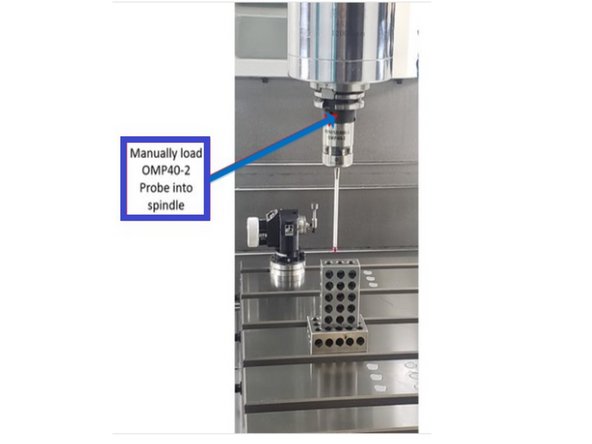
Insert the OMP40-2 into the spindle.
-
Confirm the T field shows the 3D probe tool.
-
-
-
Press [Meas. workp.].
-
Press [Calibrate probe].
-
Press [Length].
-
No calibration tool: enter the MZ1 value from Step 4 in the Z0 field.
-
Calibration tool: enter 0 in the Z0 field.
-
Jog Z down until the probe is about 0.5 in above the 1-2-3 blocks.
-
Check the setup before starting the cycle.
-
-
-
Press [CYCLE START].
-
The probe moves down, touches the top of the blocks, and measures its length.
-
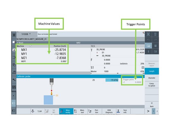
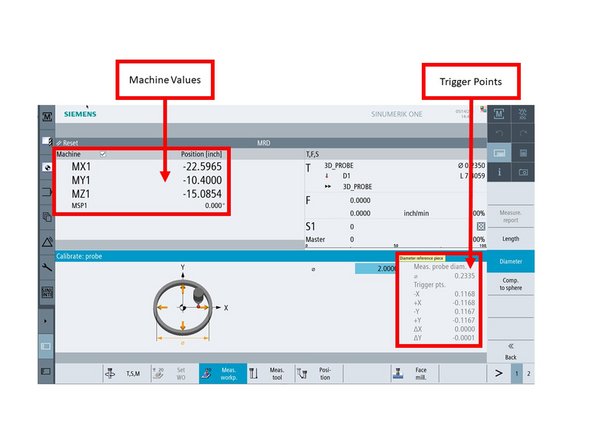
The "Calibrate: probe" window shows the machine values and trigger points.
-
Run the length calibration three times.
-
Confirm the machine values and trigger points repeat each run.
-
If they vary, lower the program feedrate and repeat.
-
-
-
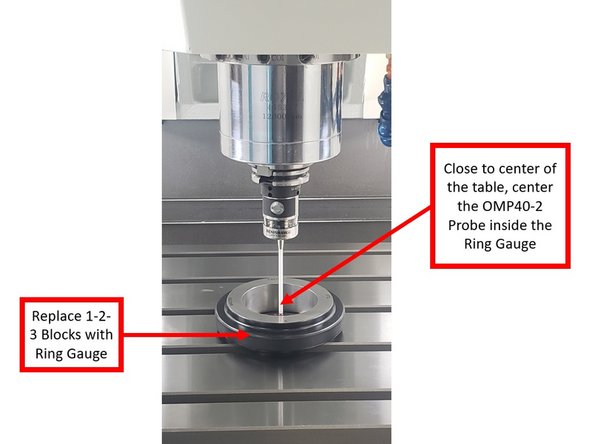
Remove the 1-2-3 blocks from the table.
-
Place the ring gauge near the center of the table.
-
Secure it with magnets or clamps so it cannot move.
-
Jog so the stylus ball sits in the center of the ring gauge, below the rim.
-
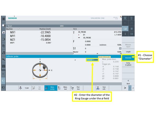
In the "Calibrate: probe" window, press [Diameter].
-
Enter the ring gauge diameter in the ø field.
-
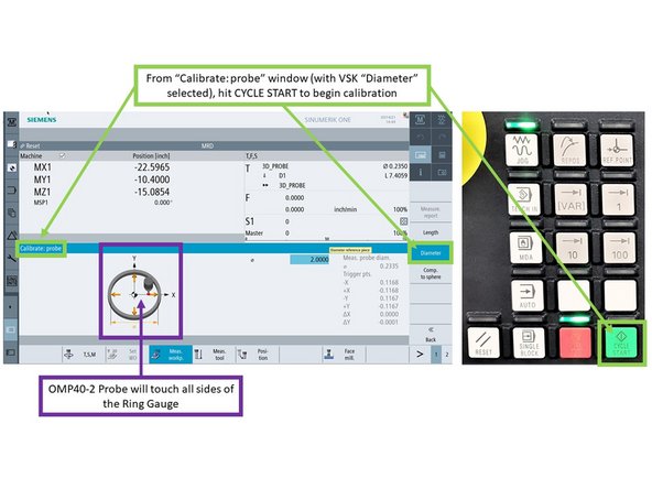
Press [CYCLE START].
-
The probe touches the inside of the ring gauge on all sides to measure diameter.
-
-
-
When the cycle finishes, the window shows the machine values and trigger points.
-
Run the diameter calibration three times.
-
Confirm the machine values and trigger points repeat each run.
-
If they vary, lower the program feedrate and repeat.
-








Attached Documents

Team