Introduction
Calibrate the OTS tool setting probe (P/N 34080-2): stylus level, then the OTS location, tool length and tool diameter. To calibrate the OMP40-2 spindle probe (P/N 34080-1), see VMCsi Probe Part Option - Calibrate Spindle Probe.
Two paths, depending on your calibration tool:
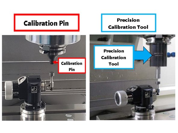
Calibration pin: Steps 6 to 10, then Step 13 onward.
Precision calibration tool: Steps 11 and 12, then Step 13 onward.
Tools
Parts
No parts specified.
-
-
The OTS must already be mounted and configured. VMCsi Probe Tool Option - Set Up Tool Setting Probe
-
You need a 0.0001 in dial indicator, metric Allen wrenches, a tool setter dial, a 1-2-3 block, and a calibration tool (pin or precision tool).
-
Recalibrate after the stylus or break stem is replaced, or after a crash.
-
-
-
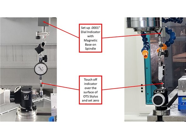
The top of the stylus must be level side to side (Y) and front to back (X).
-
Mount a 0.0001 in dial indicator in the spindle, facing forward, tip pointing down.
-
Jog until the indicator touches the top of the stylus. Zero it at the edge.
-
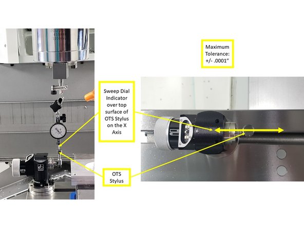
Sweep along Y. Level must be within ±0.0001 in.
-
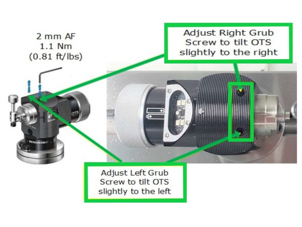
Adjust the two side set screws to level the stylus:
-
The right screw tilts the stylus right; the left screw tilts it left.
-
Adjust until level is within tolerance.
-
Torque both screws to 0.52 to 0.66 lbf-ft.
-
-
-
Sweep the indicator along X (front to back).
-
Level must be within ±0.0001 in.
-
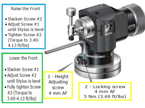
Adjust with a 4 mm Allen wrench.
-
To raise the front: loosen screw #2, adjust screw #1.
-
To lower the front: loosen screw #1, adjust screw #2.
-
Recheck level and repeat as needed.
-
When within tolerance, tighten both screws. Torque to 3.40 to 4.13 lbf-ft.
-
-
-
Required only if the calibration tool is not already in the tool list. It is usually added at the factory.
-
Press [JOG] on the MCP.
-
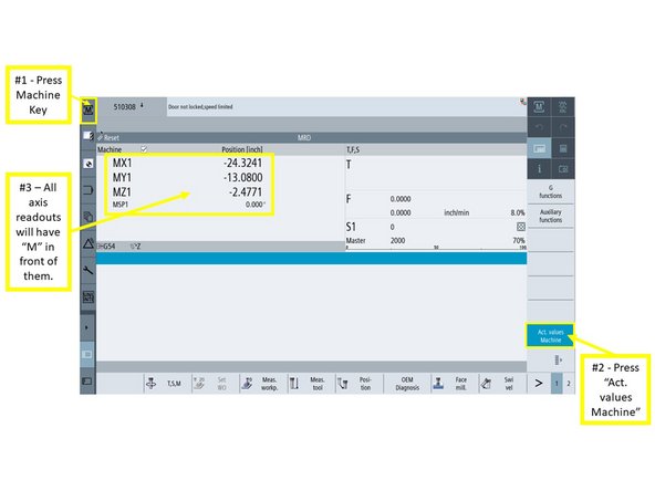
Go to [Machine] → [Act. values Machine]. Axis values now show with an "M" prefix.
-
Go to [Tool List]. Choose a location outside the ATC range: not 1 to 24 on a 24-tool ATC, not 1 to 40 on a 40-tool ATC.
-
Press [New tool].
-
Select [Spec. tool 700-900], then [725 - Calibrating tool].
-
Press [OK].
-
-
-
Choose the path for the calibration tool your shop uses. Both paths end at Step 13.
-
Calibration pin:
-
Do Steps 6 to 10, then Step 13.
-
Precision calibration tool:
-
Do Steps 11 and 12, then Step 13.
-
-
-
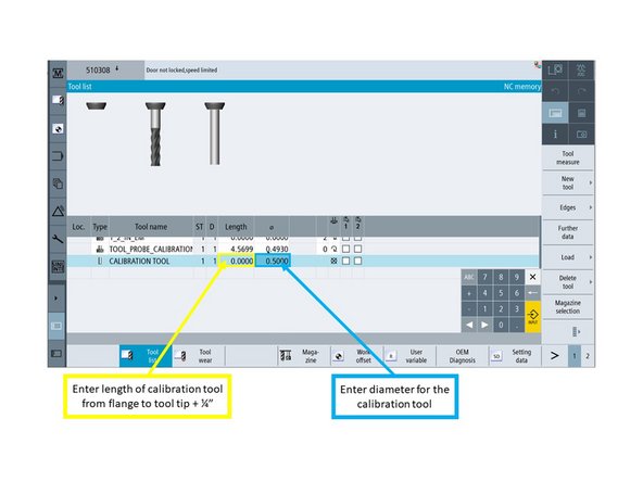
Enter the calibration pin length (flange to tip) plus 0.25 in.
-
Enter the pin diameter (for example 0.5, as shown).
-
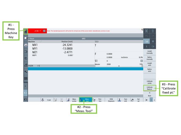
Press [Machine], then [Meas. tool].
-
Press [Calibrate fixed pt.].
-
The Z reference (fixed point) is set at the factory. Step 7 is required only if the Z reference has changed. Otherwise skip to Step 8.
-
-
-
Required only if the Z reference has changed.
-
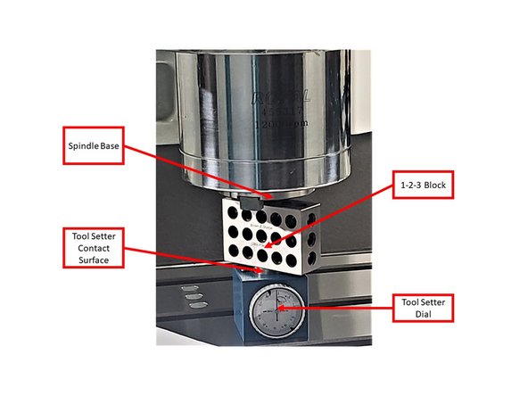
Place a tool setter dial (2 in) on a 1-2-3 block on the table, as shown.
-
Jog Z down slowly until the spindle base (not the drive keys) contacts the dial.
-
Keep jogging down until the dial reads zero.
-
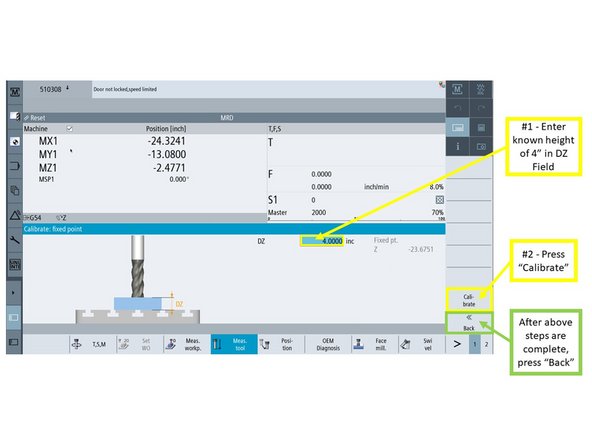
In the "Calibrate: fixed point" window, enter 4.000 in in the DZ field.
-
Press [Calibrate], then [Back].
-
-
-
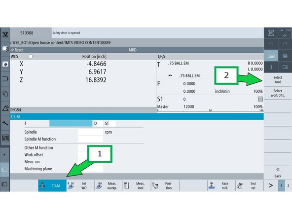
Press [T, S, M], then tap the T field.
-
Press [Select tool].
-
In the "Tool selection" window, select the calibration tool and press [OK].
-
The control prompts you to load the tool by hand.
-
-
-
Press [CYCLE START].
-
Press [DOOR OPEN] to unlock the doors.
-
Load the calibration pin into the spindle by hand, then close the doors.
-
Press [CYCLE START] again to finish the tool change.
-
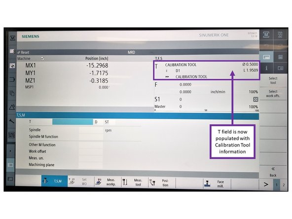
The T field now shows the calibration tool.
-
-
-
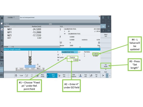
Press [Meas. tool], then [Length manually].
-
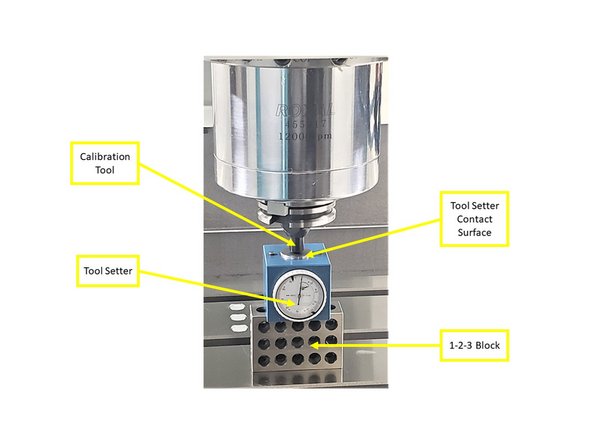
Place the tool setter dial on a 1-2-3 block on the table (4 in total).
-
Jog Z down until the dial reads zero.
-
In the "Measure: length manually" window:
-
Set Ref. point to [Fixed pt.].
-
Enter 4.000 in in the DZ field.
-
Press [Set length].
-
The L value in the tool data updates. Skip to Step 13.
-
-
-
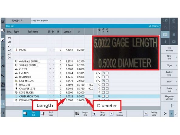
Enter the length and diameter engraved on the precision calibration tool (see image).
-
Press [JOG], then [T, S, M].
-
Press [Select tool], select the calibration tool, and press [OK].
-
-
-
Press [CYCLE START].
-
Press [DOOR OPEN] to unlock the door.
-
Load the calibration tool into the spindle by hand and close the door.
-
Press [CYCLE START] again to finish the tool change.
-
-
-
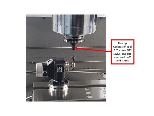
Jog the calibration tool to about 0.5 in above the stylus, centered in X and Y.
-
Press [Meas. tool], then [Calibrate probe].
-
In the "Calibrate: probe" window, press [CYCLE START].
-
The tool touches the top and sides of the stylus.
-
When it finishes, the window shows the machine values and trigger points.
-
Run the calibration three times and note the machine values and trigger points each run.
-
Confirm they repeat. If they do not, recheck stylus level (Steps 2 and 3) and repeat.
-
-
-
Press [Back], then [Length auto].
-
Press [CYCLE START].
-
The machine positions the calibration tool over the stylus and measures its length.
-
The measured length should match the value you entered. If it does not, rerun Step 13.
-
-
-
Press [Back], then [Diameter auto].
-
Press [CYCLE START].
-
The machine measures the tool diameter and logs it.
-
The measured diameter should match the tool table value. If it does not, rerun Step 13.
-









Attached Documents

Team