Introduction
This guide explains how to mount the OMI-2T Probe Receiver Assembly (P/N: 34080-10) on all VMCsi models.
The OMI-2T Probe Receiver is a required component for both the Probe Part and Probe Tool options. Links to the installation and calibration procedures for both options are provided in the final step of this guide.
Additional reference materials are included at the end of the guide. These include the Part Number 34050 document and the OMI-2T instruction manual, which show the location of all components and explain how the Probe Receiver Assembly is put together.
-
-
To install the OMI-2T Receiver Assembly (P/N: 34080-10), tap M6 holes in the following locations:
-
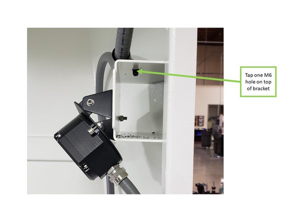
Tap one M6 hole on top of the bracket next to the left-side door, from inside the machine.
-
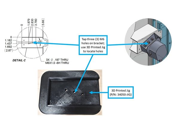
Tap three M6 holes on the front face of the same bracket, as shown in the image. The OMI-2T will mount here.
-
Use the 3D Printed Jig (P/N: 34050-JIG) to locate the three mounting holes on the bracket.
-
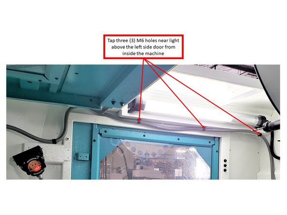
Tap three M6 holes near the light above the left-side door, from inside the machine.
-
Some machines may come with these holes pre-tapped.
-
-
-
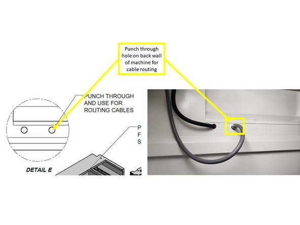
Punch a through-hole in the back wall of the machine for cable routing (see image).
-
For VMC7si and VMC10si models, these holes are located near the bracket in the top left corner of the back wall.
-
For VMC12si and VMC14si models, the holes are positioned at the very top left corner of the back wall, where no bracket is present.
-
-
-
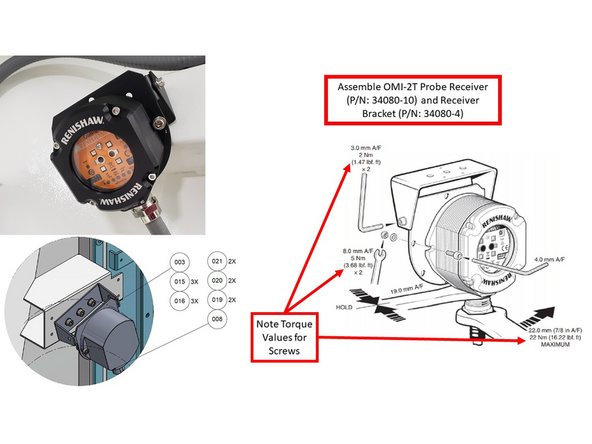
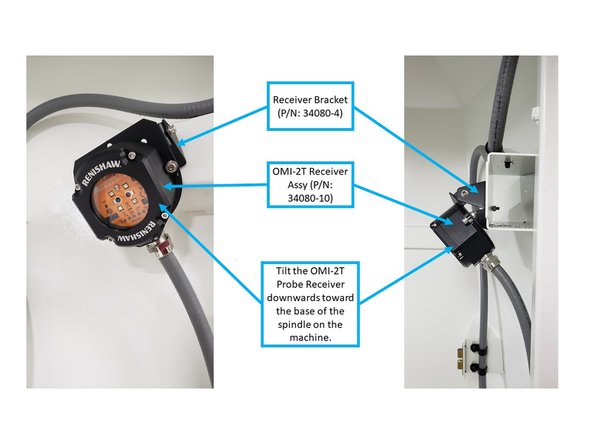
With the use of two (2) M5 screws, washers, and Nylon lock nuts (provided by Renishaw), fasten the OMI-2T Receiver Assy to the Receiver Bracket (P/N: 34080-4).
-
Apply a torque of 3.68 lbf-ft.
-
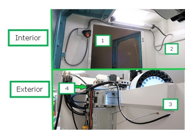
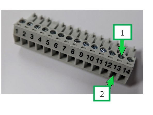
Route the cables from the receiver mount (1) along the left interior wall to the rear wall (2), exiting out the back.
-
Continue routing the cables from the exterior rear (3) into the cable channel (4) leading to the electrical cabinet.
-
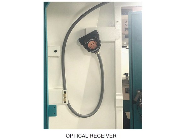
Mount the OMI-2T Receiver and Bracket to the machine using three M6 screws (P/N: M6 12 27B) and serrated washers (P/N: 24009-3).
-
Fasten to the three M6 tapped holes previously added to the interior bracket.
-
Tilt the receiver downward toward the base of the spindle.
-
Ensure the receiver is oriented as shown in the image to prevent coolant from entering through the core openings.
-
-
-
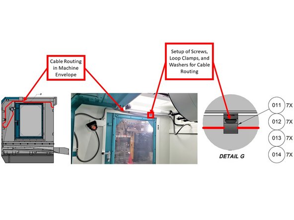
Refer to the first image for proper cable routing and the correct placement of loop clamps, screws, and washers.
-
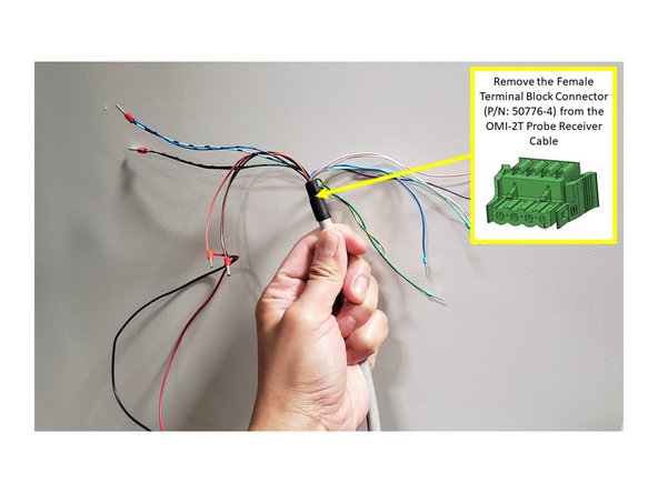
Before routing the cable, remove the Female Terminal Block Connector (P/N: 50776-4) from the end of the OMI-2T cable, and tape the wires together to help the cable pass through the knockout hole and machine cable troughs.
-
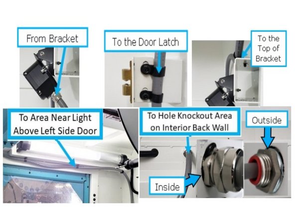
After the OMI-2T is mounted near the left-side door, route the cable to the front door latch from inside the machine.
-
Remove the two screws from the door latch, attach two loop clamps to hold the cable in place, and reinstall the screws.
-
Route the cable from the door latch back to the top of the bracket where the OMI-2T is installed. Use one M6-1.0x10 (27B) screw, one washer, and one loop clamp to secure it.
-
Continue routing the cable up to the three tapped M6 holes near the light above the left-side door. Use three M6-1.0x10 (27B) screws, three washers, and three loop clamps.
-
Guide the cable through the knockout hole on the back interior wall of the machine.
-
Install the fitting with seal (P/N: 34080-6) when routing the cable through this hole. Refer to the inset images for proper assembly.
-
-
-
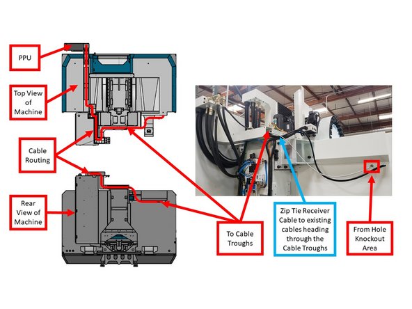
From the knockout hole, zip tie the OMI-2T cable to existing cables leading toward the cable troughs.
-
Route the cable through the cable troughs from the back of the machine to the PPU.
-
Follow the existing cable paths inside the enclosed cable troughs for a clean and secure installation.
-
-
-
Remove the tape from the colored wires on the OMI-2T Probe Receiver cable.
-
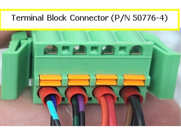
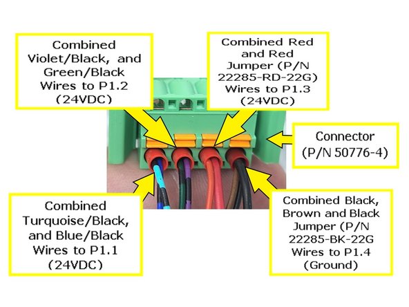
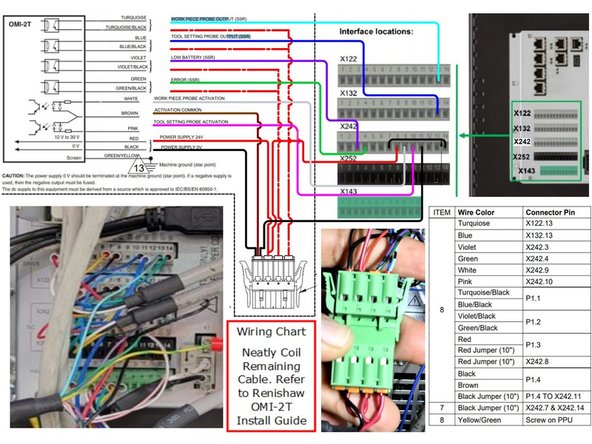
Reconnect the wires to the Female Terminal Block Connector (P/N: 50776-4) as shown in the image.
-
Install the Turquoise/Black and Blue/Black wires into Position 1 (P1.1).
-
Install the Violet/Black and Green/Black wires into Position 2 (P1.2).
-
Install the Red and Red Jumper Wires (P/N: 22285-RD-22G) into Position 3 (P1.3).
-
Install the Black, Brown, and Black Jumper Wires (P/N: 22285-BK-22G) into Position 4 (P1.4).
-
-
-
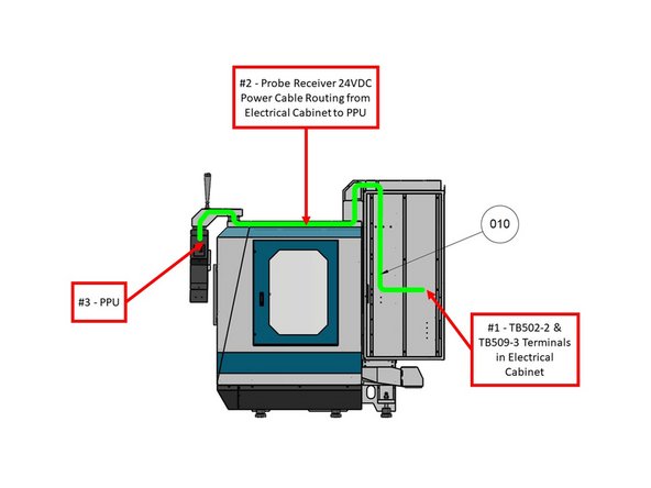
Route the Probe Receiver 24VDC Power Cable (P/N: 31594-2) from the electrical cabinet to the PPU using the cable troughs.
-
Refer to the first image on the left (with the green line) for the recommended cable path.
-
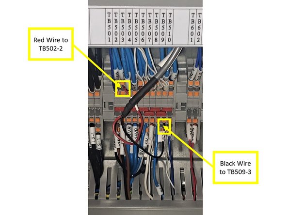
Connect the Red wire (24VDC) to TB502-2.
-
Connect the Black wire (Ground) to TB509-3.
-
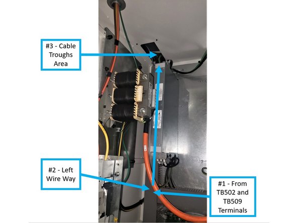
From terminals TB502 and TB509, guide the cable through the left wireway and into the cable troughs toward the PPU.
-
-
-
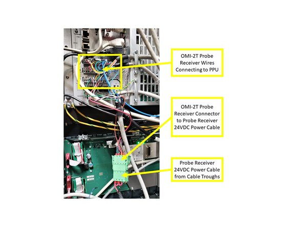
From the cable troughs, connect the Probe Receiver 24VDC Power Cable to the OMI-2T Receiver Assembly Cable.
-
Neatly coil and store both cables inside the pendant housing.
-
The OMI-2T Receiver Cable must connect to both the Power Cable and the PPU.
-
Refer to the second image on the left for the Wiring Interconnections Chart, which shows how to connect the OMI-2T Receiver Cable to the PPU and Power Cable.
-
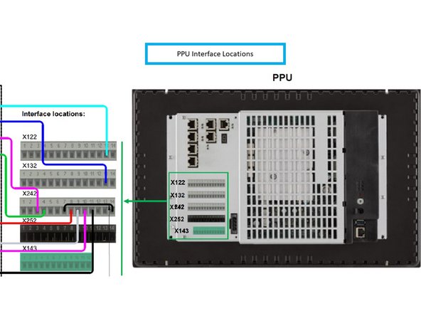
Refer to the third image on the left for the PPU Interface Terminal Block designations.
-
Terminal blocks X122, X132, X242, and X252 each have 14 terminals. X143 has 12 terminals.
-
Each terminal block can be removed and reinstalled to simplify the wiring process.
-
-
-
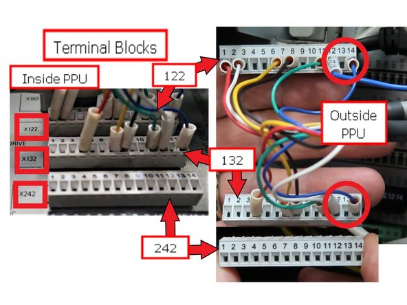
Connect the OMI-2T Receiver Cable to terminal blocks X122, X132, and X242 in the PPU.
-
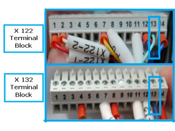
Refer to the image for wire positions. Note: terminals X122 and X132 have a wire missing from position 13 (circled for clarity).
-
To install a wire:
-
Loosen the terminal screw.
-
Insert the wire into the terminal.
-
Retighten the screw to secure the connection.
-
-
-
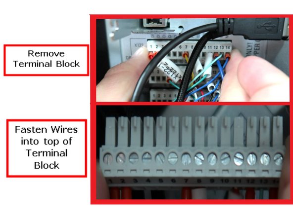
You may need to remove the terminal blocks from the PPU to install the wires properly.
-
To remove a terminal block, do not squeeze the ends. Hold the ends firmly and pull while gently wiggling it free. There are no retainer clips—just a tight fit.
-
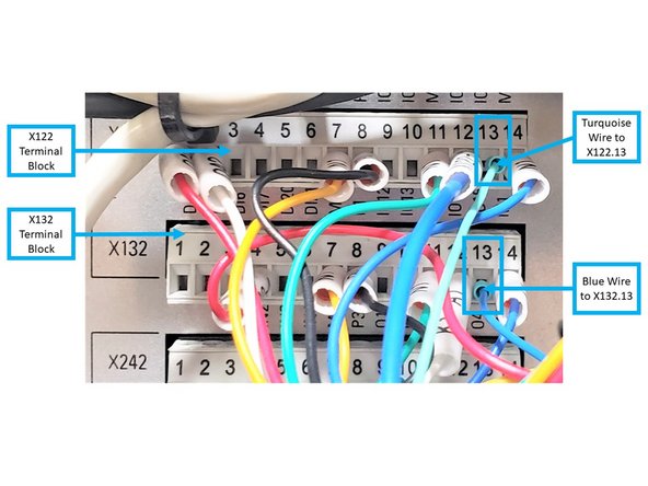
Refer to the images showing the terminal blocks installed in the PPU and the specific wiring positions.
-
The second image provides a close-up of the wire locations for clarity.
-
On Terminal Block X122, install the Turquoise wire from the OMI-2T Receiver Cable to X122.13.
-
On Terminal Block X132, install the Blue wire to X132.13.
-
-
-
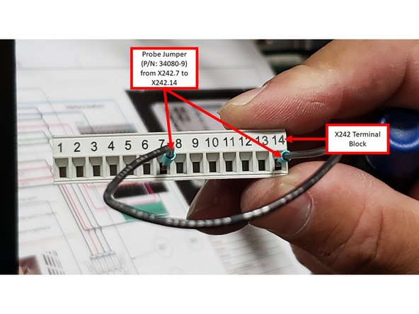
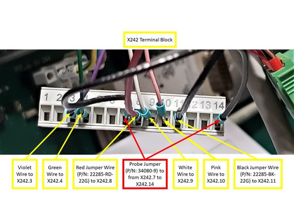
On Terminal Block X242, install the Probe Jumper Wire (P/N: 34080-9) between X242.7 and X242.14.
-
Connect the Violet wire to X242.3 and the Green wire to X242.4.
-
Connect the White wire to X242.9 and the Pink wire to X242.10.
-
Route the Red Jumper Wire (P/N: 22285-RD-22G) from Position 3 of the OMI-2T Receiver Terminal Block Connector to X242.8.
-
Route the Black Jumper Wire (P/N: 22285-BK-22G) from Position 4 of the same connector to X242.11.
-
Reinstall all terminal blocks into the PPU.
-
-
-
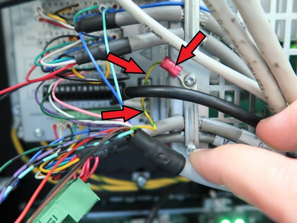
Install the Green/Yellow wire to the machine ground using a Torx T10 screw, as shown in the image.
-
-
-
The OMI-2T Probe Receiver is a required component for the Probe Part and/or Probe Tool Options:
-
For more information about the installation of the OMP40-2 Probe (P/N: 34080-1), please refer to the following link:
-
-
For more information about the installation of the OTS Probe (P/N: 34080-2), please refer to the following link:
-
VMCsi Probe Tool Option - Set Up & Calibrate Tool Setting Probe
-