
Introduction
This guide explains how to install and calibrate the OTS Probe (P/N: 34080-2) on all VMCsi models.
The OTS Probe requires a receiver to communicate with the Siemens control. If the receiver has not yet been installed, refer to the guide titled “VMCsi Probe Tool and Probe Part Options – Mount Probe Receiver” before proceeding.
Additional reference materials, including the Part Number 34050 document and the OTS instruction manual, are available at the end of this guide. These documents show where each component is located and how the system is assembled.
Tools
Parts
No parts specified.
-
-
Insert the Break Stem through the Captive Link, then install both onto the OTS body, as shown in the first image.
-
Use a 5mm Allen wrench to tighten the Break Stem. Torque to 1.84–1.99 lbf-ft.
-
Bend the Captive Link upward after installing the Break Stem.
-
Install the Stylus onto the Coupler, then tighten Set Screw #1 (top screw for the stylus) using a 2mm Allen wrench. Torque to 0.74–0.89 lbf-ft.
-
Insert the Cap Screw through the bent Captive Link and secure it to the bottom of the Coupler using the Support Bar and a 3mm Allen wrench. Torque to 1.84–1.99 lbf-ft.
-
Tighten Set Screw #2 (bottom screw for the Cap Screw) with the Support Bar and a 2mm Allen wrench, as shown in the second image. Torque to 0.74–0.89 lbf-ft.
-
Always hold the Support Bar in position to counteract twisting forces, and avoid over-stressing the Break Stem.
-
-
-
Twist off the battery cover on the OTS Probe to remove the batteries.
-
Wait approximately 5 seconds, then reinsert the batteries and twist the cover back on to secure them.
-
Do not allow coolant or debris to enter the battery compartment.
-
The LEDs on the OTS will flash red, then green, then blue. When this sequence appears, immediately deflect and hold the stylus to enter configuration mode.
-
Do not remove the batteries while in configuration mode. To exit, leave the stylus untouched for more than 20 seconds.
-
The probe will now flash the battery status:
-
5 red flashes = batteries are good
-
Repeating red + blue flash = batteries are low and should be replaced
-
-
-
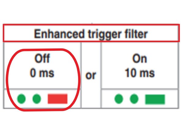
While holding the stylus deflected, the Enhanced Trigger Filter setting will appear. Release the stylus to proceed.
-
LEDs will flash green twice, followed by a long red flash to indicate the Advanced Trigger Filter is active.
-
Once the Enhanced Trigger Filter is confirmed off (0 ms), deflect and hold the stylus for more than 4 seconds to move to the next menu.
-
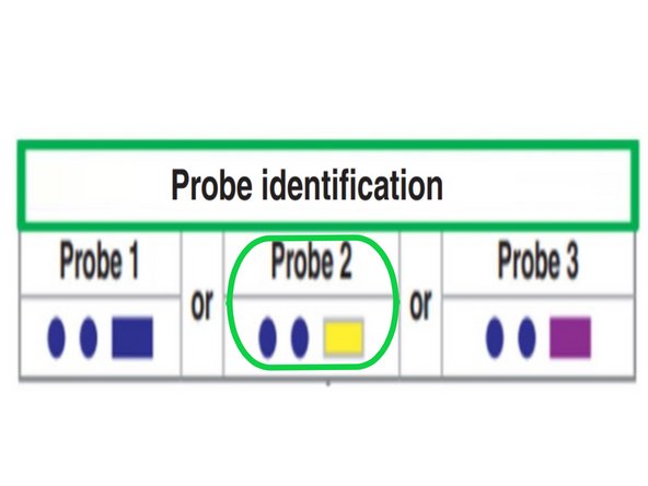
For probe identification, LEDs will flash blue, blue, yellow. If a different sequence appears (e.g., blue or purple), deflect and release the stylus after 1 second to cycle through settings.
-
When blue, blue, yellow is shown, deflect and hold the stylus for more than 4 seconds to proceed.
-
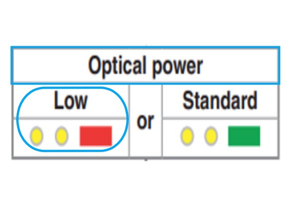
For optical power setting, deflect and release the stylus until you see two yellow flashes, followed by a long red flash.
-
Leave the stylus untouched for more than 20 seconds to confirm all settings.
-
-
-
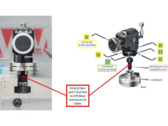
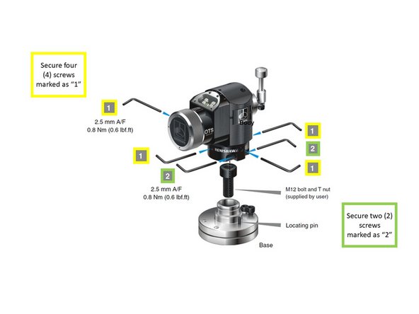
Use a 2.5 mm Allen wrench to loosen the four screws labeled "1" to separate the OTS Body from the Base (see first image).
-
Loosen the two screws labeled "2" to allow the base to mount freely.
-
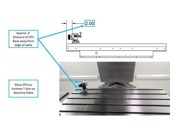
Insert the M12 bolt and T-slot nut into the OTS Base and secure it to the machine table.
-
Position the OTS on the furthest T-slot, approximately 2 inches from the left edge of the table, avoiding any potential collision paths (see second image).
-
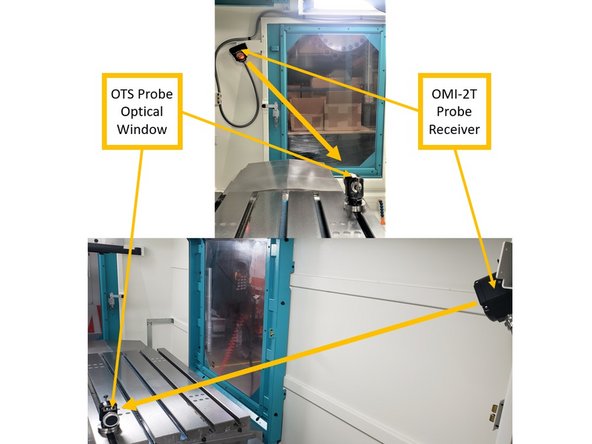
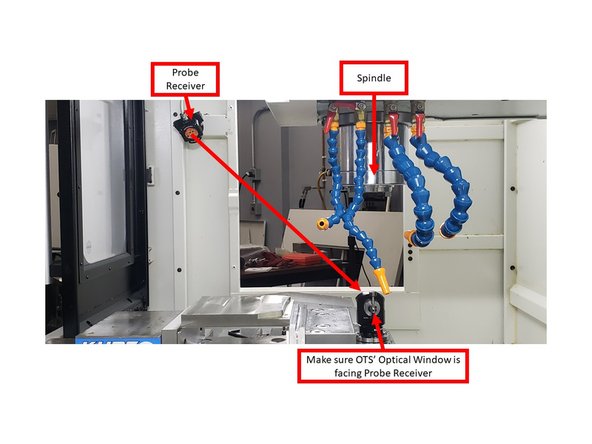
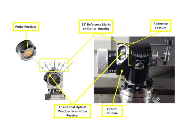
Ensure the Optical Window of the OTS is facing the OMI-2T Probe Receiver.
-
-
-
Reinstall the OTS Body onto the Base by tightening the four screws labeled "1". Torque to 0.6 lbf-ft.
-
Tighten the two screws labeled "2". Torque to 0.6 lbf-ft.
-
-
-
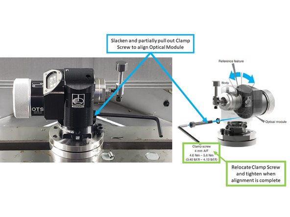
The OTS Optical Module can be set in seven positions, each spaced 15° apart, to align the Optical Window with the Probe Receiver.
-
Jog the table until the OTS is directly under the spindle. This will be the tool touch-off position and must be in the line of sight of the Probe Receiver.
-
Use a 4 mm Allen wrench to slacken and partially remove the Clamp Screw.
-
Rotate the Optical Module by aligning a 15° reference mark on the housing with the reference feature on the body.
-
Continue rotating until the Optical Window lines up as closely as possible with the Probe Receiver.
-
Reinsert the Clamp Screw and torque it to 3.7 lbf-ft to lock the position.
-
-
-
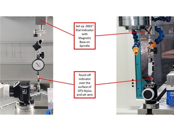
The top of the OTS Stylus must be level side to side (Y Axis) and front to back (X Axis).
-
Mount a .0001" dial indicator in the spindle, facing forward with the tip pointing down.
-
Jog the head until the indicator contacts the top of the stylus. Zero the indicator at the edge.
-
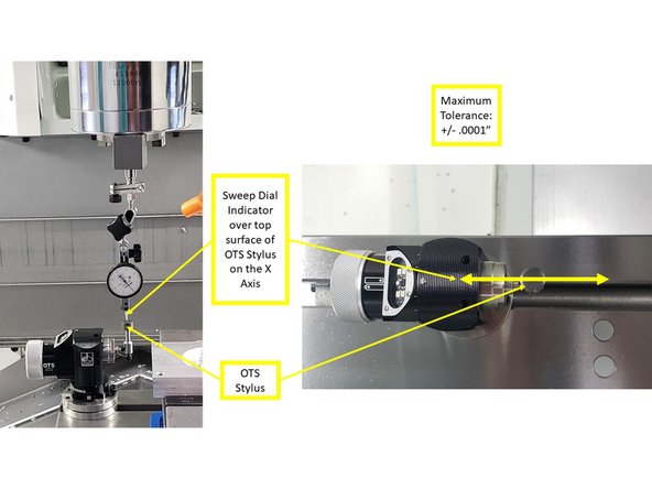
Sweep across the Y Axis and check for flatness. Tolerance is ±0.0001".
-
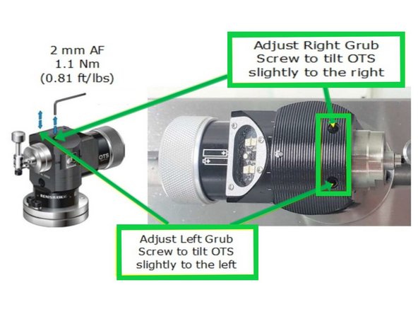
Adjust the two side set screws to level the stylus:
-
Right screw tilts the stylus to the right; left screw tilts it to the left.
-
Adjust until level is within tolerance.
-
Torque both screws to 0.52–0.66 lbf-ft.
-
-
-
Use the dial indicator to sweep across the stylus along the X Axis (front to back).
-
Maximum allowable deviation is ±0.0001".
-
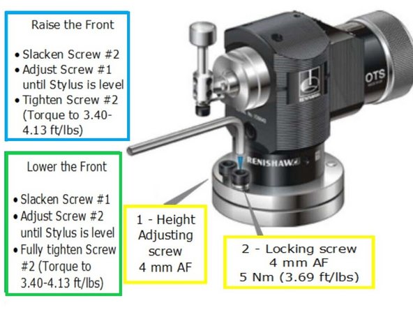
Use a 4 mm Allen wrench to make adjustments.
-
To raise the front: loosen Screw #2, adjust Screw #1.
-
To lower the front: loosen Screw #1, adjust Screw #2.
-
Recheck level and repeat adjustments as needed.
-
Once within tolerance, tighten both screws.
-
Torque to 3.40–4.13 lbf-ft.
-
-
-
These steps are only needed if not already completed at the factory.
-
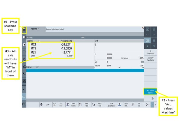
On the MCP, press [JOG].
-
On the touchscreen, press [Machine], then select [Act. values Machine].
-
Axis values will now display with an “M” prefix.
-
Press [Tool List], then select a location outside of ATC tool positions (#1–24).
-
Press [New tool] on the right-side soft keys.
-
Select [Spec. tool 700–900], then choose [725 – Calibrating tool] from the menu.
-
Press [OK] to add the calibration tool to the list.
-
-
-
These are factory-set defaults and typically do not need to be changed unless the Z Reference has been modified.
-
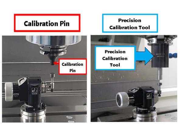
Choose the type of calibration tool used by your shop.
-
Calibration Pin:
-
Use Steps 11 - 15
-
Precision Tool:
-
Use Steps 16 - 17
-
-
-
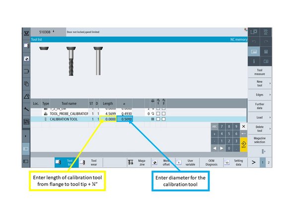
With the calibration tool added, enter its length (flange to tip) plus 0.25".
-
Enter the diameter of the calibration tool (e.g., "0.5" as shown in the image).
-
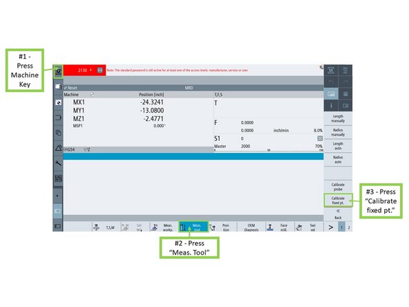
Press [Machine], then press [Meas. tool].
-
Press [Calibrate fixed pt.] to set the Z Reference point.
-
This calibration is factory-set and does not need to be redone unless Z Reference has changed.
-
-
-
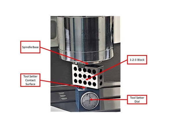
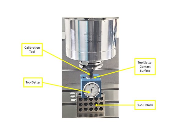
Place a Tool Setter Dial (2" height) on top of a 1-2-3 Block on the machine table, as shown.
-
Jog the Z Axis down slowly until the spindle base (not the drive keys) contacts the block.
-
Continue jogging down until the dial reads zero.
-
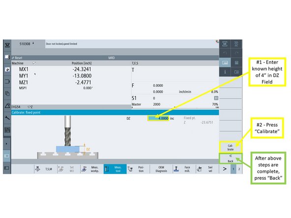
In the [Calibrate: fixed point] window, enter 4.000" in the DZ field.
-
Press [Calibrate], then press [Back] when complete.
-
-
-
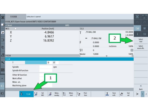
Press [T,S,M], then tap the [T] field.
-
Press [Select Tool].
-
In the [Tool selection] window, select the Calibration Tool, then press [OK].
-
The control will prompt you to load the tool into the spindle manually.
-
-
-
Press [CYCLE START] on the MCP to begin the tool load prompt.
-
Press [DOOR OPEN] to unlock the doors.
-
Manually load the Calibration Tool into the spindle, then close the doors.
-
Press [CYCLE START] again to confirm the tool change.
-
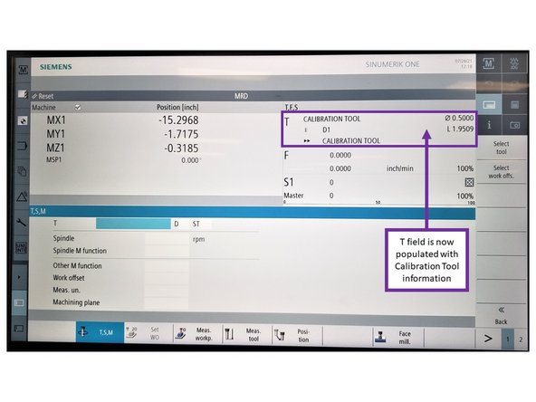
The [T] field under [T,F,S] will now display the Calibration Tool.
-
-
-
Press [Meas. tool], then press [Length manually].
-
Place the Tool Setter Dial on top of a 1-2-3 Block on the table (total height = 4").
-
Jog the Z Axis down until the dial reads zero.
-
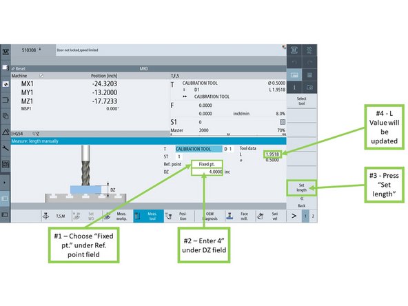
In the [Measure: length manually] window:
-
Set Ref. point to [Fixed pt.]
-
Enter 4.000" in the DZ field.
-
Press [Set length].
-
The L Value in the Tool data section will update automatically.
-
-
-
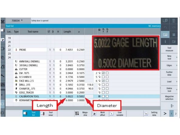
Enter the length and diameter of the calibration tool using the pop-up keypad.
-
Refer to the engraving on the tool for measurement values (see image).
-
Press [JOG], then [T,S,M].
-
Press [Select Tool], choose the Calibration Tool, and press [OK].
-
-
-
Press [CYCLE START] on the MCP to begin the tool load prompt.
-
Press [DOOR OPEN] to unlock the machine door.
-
Manually load the calibration tool into the spindle and close the door.
-
Press [CYCLE START] again to complete the tool change.
-
-
-
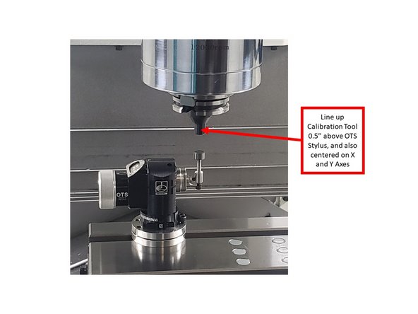
Jog the Calibration Tool to about 0.5" above the OTS Stylus, centered in X and Y.
-
Press [Meas. tool], then press [Calibrate probe].
-
When the [Calibrate: probe] window appears, press [CYCLE START].
-
The tool will automatically touch the top and sides of the stylus.
-
When calibration is complete, the window will display Machine Values and Trigger Points.
-
Run this calibration process three times to verify consistent results.
-
Note the Machine Values and Trigger Points after each run.
-
-
-
Press [Back], then press [Length auto].
-
Press [CYCLE START] on the MCP.
-
The machine will automatically position the Calibration Tool above the stylus and measure tool length.
-
After the cycle completes, the tool length should match the value originally entered.
-
-
-
Press [Back], then press [Diameter auto].
-
Press [CYCLE START] on the MCP.
-
The machine will automatically measure the tool's diameter and log the result.
-
The measured diameter should match the value entered in the tool table.
-


![On the MCP, press [JOG].](https://d3t0tbmlie281e.cloudfront.net/igi/trakmtsupport/F2UAZQxWDVnQK6h6.medium)
![On the touchscreen, press [Machine], then select [Act. values Machine].](https://d3t0tbmlie281e.cloudfront.net/igi/trakmtsupport/rWWFbCUTr3MdXSJC.medium)
![Press [T,S,M], then tap the [T] field.](https://d3t0tbmlie281e.cloudfront.net/igi/trakmtsupport/bwFAOqGRUaOWWFPV.medium)
![Press [Select Tool].](https://d3t0tbmlie281e.cloudfront.net/igi/trakmtsupport/ghDfrEtQiFfZYDEZ.medium)
![In the [Tool selection] window, select the Calibration Tool, then press [OK].](https://d3t0tbmlie281e.cloudfront.net/igi/trakmtsupport/OF6D5fWkOxShdruK.medium)
![Press [CYCLE START] on the MCP to begin the tool load prompt.](https://d3t0tbmlie281e.cloudfront.net/igi/trakmtsupport/pq6LaoAT3CuH3Gyo.medium)
![Press [DOOR OPEN] to unlock the doors.](https://d3t0tbmlie281e.cloudfront.net/igi/trakmtsupport/lKgkyYmyypK6KuB6.medium)
![Press [Meas. tool], then press [Length manually].](https://d3t0tbmlie281e.cloudfront.net/igi/trakmtsupport/6FGFSPHyRdZSADAj.medium)
![Press [JOG], then [T,S,M].](https://d3t0tbmlie281e.cloudfront.net/igi/trakmtsupport/ww36NTLwXtPRBHy1.medium)
![Press [CYCLE START] on the MCP to begin the tool load prompt.](https://d3t0tbmlie281e.cloudfront.net/igi/trakmtsupport/1ltn2dFyT6ZO1TFL.medium)
![Press [DOOR OPEN] to unlock the machine door.](https://d3t0tbmlie281e.cloudfront.net/igi/trakmtsupport/aw2QXEuObxYMd2eT.medium)
![Press [Meas. tool], then press [Calibrate probe].](https://d3t0tbmlie281e.cloudfront.net/igi/trakmtsupport/gFcHH1NUYGhyMvBv.medium)
![When the [Calibrate: probe] window appears, press [CYCLE START].](https://d3t0tbmlie281e.cloudfront.net/igi/trakmtsupport/L6FEuhanLHDhCAnF.medium)
![Press [Back], then press [Length auto].](https://d3t0tbmlie281e.cloudfront.net/igi/trakmtsupport/XWtaq5RYadU2DHIn.medium)
![Press [CYCLE START] on the MCP.](https://d3t0tbmlie281e.cloudfront.net/igi/trakmtsupport/hKK1bVwNDSHVpEZX.medium)
![Press [Back], then press [Diameter auto].](https://d3t0tbmlie281e.cloudfront.net/igi/trakmtsupport/vWKvsZTsM1ZVYSnO.medium)
![Press [CYCLE START] on the MCP.](https://d3t0tbmlie281e.cloudfront.net/igi/trakmtsupport/Fp5YYgQQcayYIhuS.medium)