Introduction
This version of EHW installation has been simplified for the TRAK side of the work to be done.
-
-
TMC has the option to have X, Y and Z handwheels included with your mill. The handwheels are mounted on the rail in front of the machine.
-
To Install:
-
The TMC's option key must be programmed to include this option. Under STATUS, the user can also turn the EHW’s on and off. See Step 14 for location.
-
Electronic Hand Wheels are a proprietary option on a wide range of TRAK Mills, which provide a high level of precise control over the movement of X, Y and Z axis while providing a high level of protection for the operator. EHW's allow for control of each individual axis while also incorporating the TRAKing feature.
-
Our ProtoTRAK software provides control of these handwheels at various speeds. There is a fast course mode to allow rapid movement on a mill when not close to a work area or other objects. We also provide precise fine control over the hand wheels when needed for slow accurate movement while zeroing out an axis as well as other tasks.
-
A valuable reference is provided, see the available pdf drawings at the end of this guide.
-
Safety First - While working on our equipment: Turn power off and remove power source from the mill.
-
-
-
SAFETY ITEM – Turn Off Power to Mill. Disconnect Power Cable from Mill.
-
Remove "WARNING Do not operate before shutting door." sign below front door. Four holes are to be sealed from the rear with silicone.
-
If no label, skip this step.
-
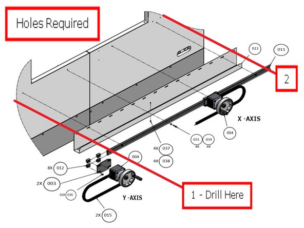
Drill holes for the X & Y Axis along the front panel as shown. Dimensions are measured from the left front edge of the TMC.
-
In the case of a factory install of the EHW option, a jig is available to place in the front door opening with a template to drill the holes for the X/Y EHW without spending time measuring the hole locations.
-
-
-
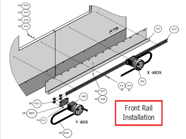
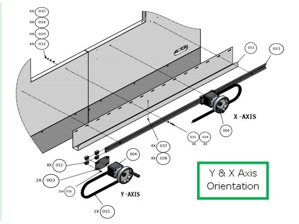
Illustrated are the hardware requirements to attach the front rail, cable channel and EHWs to the front of the mill. Refer to the Parts list in the rear of the document for the hardware detail needed in the steps.
-
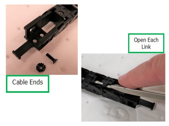
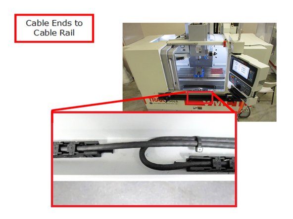
X & Y EHWs need to have their electronic cable installed into the cable carrier chain by prying each link as shown. The ends of both cable carriers have different genders as needed. Attach cable ends to each cable carrier by prying. Attach EHW to double rail.
-
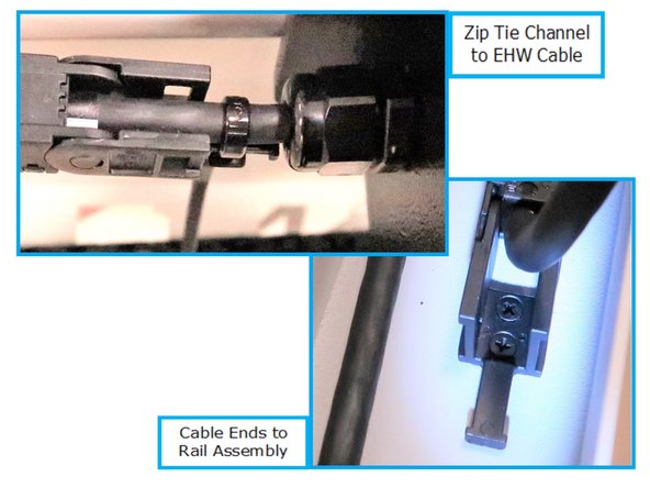
Attach cable carrier with electronic cable to EHW on rail. At the EHW end of the cable carrier a Zip Tie is used on the cable end tab to attach to the cable. The rail end of the cable carrier is attached to the rail with two screws and locking nuts.
-
-
-
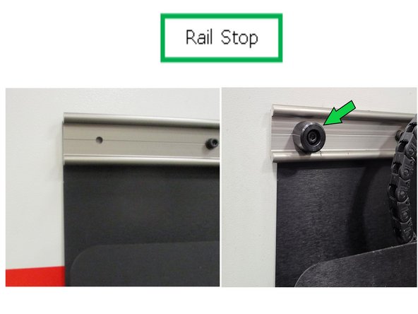
Drill 2 - 0.261 holes through the existing rail holes at each end of the rail.
-
Use M6 screw to attach metal rail stop to both ends of the rail.
-
-
-
The X Axis cable at the cable rail end is bent over the Y axis cable and then tie banded together.
-
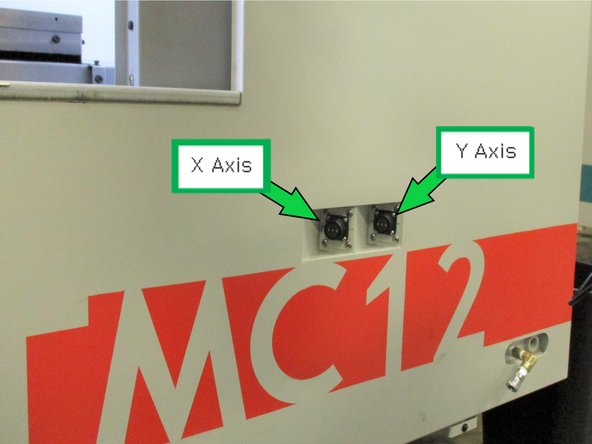
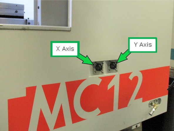
Plug EHW Cables as shown.
-
If connectors are reversed, swap connections at the electrical cabinet.
-
-
-
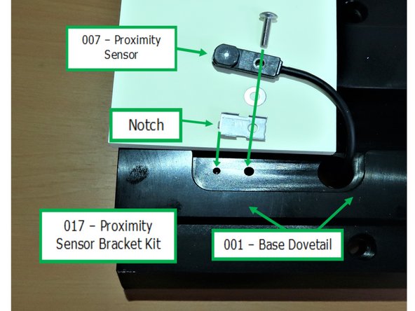
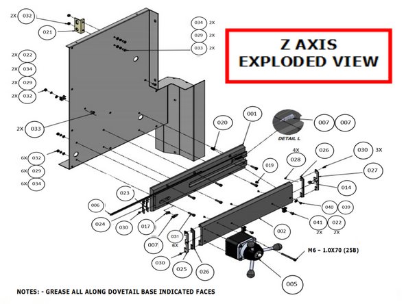
Install the Proximity Sensors pair (Part Number 7) into the Base Rail (Part Number1) using the holes matching the location of the sensor wires on the spindle side cover as shown.
-
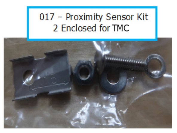
Proximity Sensor kit order of assembly. Lock washer and nut are not used from kit. M3 screw goes into sensor, flat washer between sensor and bracket, and then attach assembly into base dovetail. Notch on bracket slides into hole on dovetail.
-
Manufacturing has recorded errors indicating a malfunction of either one of the sensors. This has been corrected by putting a washer behind the sensor bracket and reassembling the problem sensor. This makes the sensor closer to the moving rail.
-
Part number 017 is supplied in a bag and contains an assortment of 5 parts as shown. Two kits are supplied for the front and rear sensors.
-
-
-
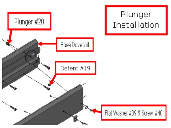
Insert Plunger # 20 and place flush to top of base.
-
Plunger is installed from back of dovetail base BEFORE mounting dovetail base to spindle side cover. Plug in Plunger # 20 to the detent, screw in and then mount.
-
Refer to McMaster #3382A16 plunger drive in order to adjust spring plunger # 20 from front side of dovetail base. (Plunger drive not included with installation kit).
-
-
-
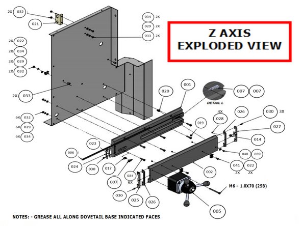
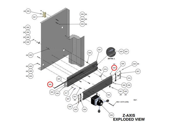
There are 6 PEM nuts pre-installed to attach the Z Axis. They are for fastening the Dovetail Base to Spindle Side Cover.
-
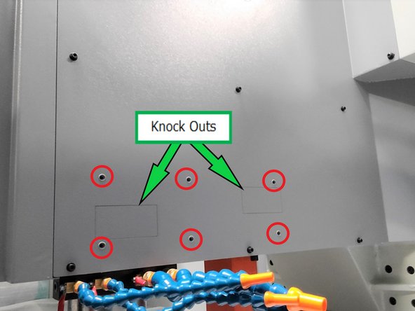
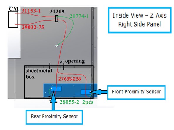
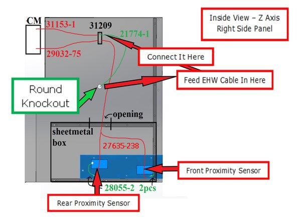
Remove the two knockouts shown for front and rear proximity sensors. The knockouts are provided to attach the front and rear proximity sensors to their electric connections inside the spindle cover.
-
Here is the inside view of the right side spindle sheet metal. Access to these connections can be made from the top or bottom of the spindle without panel removal.
-
Connect the adjacent proximity sensor cable to the connector inside the spindle cover through each knockout.
-
Mount Dovetail base to sheet metal using 6 M6-1.0x25SHCS.
-
-
-
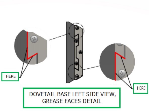
Lube the Dovetail base all along surfaces in red on the Gibs using any water-resistant bearing grease that conforms to ISO VG 68 to 100 standard.
-
Assemble the remaining parts including wipers, wiper stop, etc., as referenced.
-
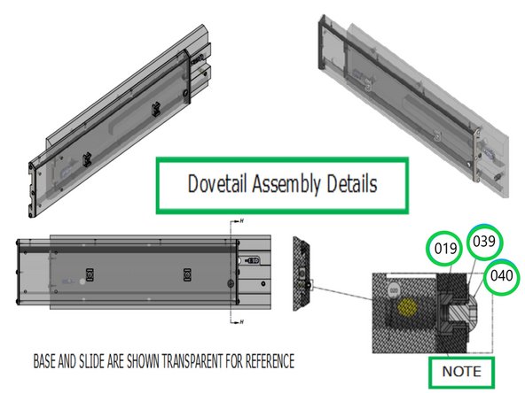
Assemble parts Detent #19, Flat Washer 10 70B #39, and 10-32x14 BHCS #40 but do not tighten Screw # 40. Adjust slide and base so that all items are aligned, then tighten part 40.
-
Attach the Z EHW to the Slider Dovetail (Part Number 2) with the specified hardware. The Z Axis cable remains loose and will be attached directly to the spindle side later.
-
Adjust plunger and detent engagement as necessary.
-
-
-
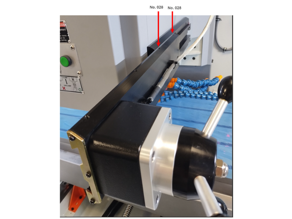
Tighten the back two Item No. 028 set screws to put slight pressure on the Item No. 006 Gib-Slider.
-
Dove Tail should feel supported when extended out, and not "rock" down while extending.
-
Front two Item No. 028 set screws should not be putting any pressure on the Item No. 006 Gib-Slider at any time.
-
-
-
Remove round knockout for Z EHW cable.
-
Feed the EHW cable 21774-1 from the outside into the opening at about the center of the panel.
-
Tighten the liquid tight fitting.
-
The electric cable connects to 31209 mount at the top inside of the panel.
-
You can access the connector from the outside of the spindle without removal of the right side cover by fully lowering the Z axis.
-
-
-
Test all three axis at different speeds and make sure they work correctly.
-
Z Axis operates from the spindle, reposition dovetail and retry.
-
Make sure Z EHW proximity sensors trigger when dovetail is removed from parked position (pushed all the way in).
-
Attached Documents
One Comment
I need to have you add a note about the end stops. I will email you a picture. The TMC 12/14 door opening is wide, and the bumpers stop the X/Y EHW from being pushed off the railing and falling off.
Dylan Harter - Resolved on Release Reply


