Introduction
This procedure re-establishes the absolute encoder reference, and therefore machine zero, on a TC820si and a TC820LTYsi. It covers three servo axes: Q, X and Z1.
For a TC820LTY-Ssi, use the TC820LTY-Ssi guide instead. That machine has a sub spindle, a second Z axis and a different Z1 datum, and none of it is covered here.
Tools
Parts
No parts specified.
-
-
This procedure overwrites machine zero on X and Z1. The archive is the only way back to the machine's current state.
-
Create a complete machine archive before touching anything.
-
-
-
-
Press [JOG] and [REF POINT] on the MCP.
-
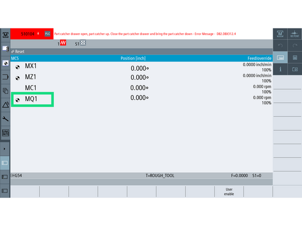
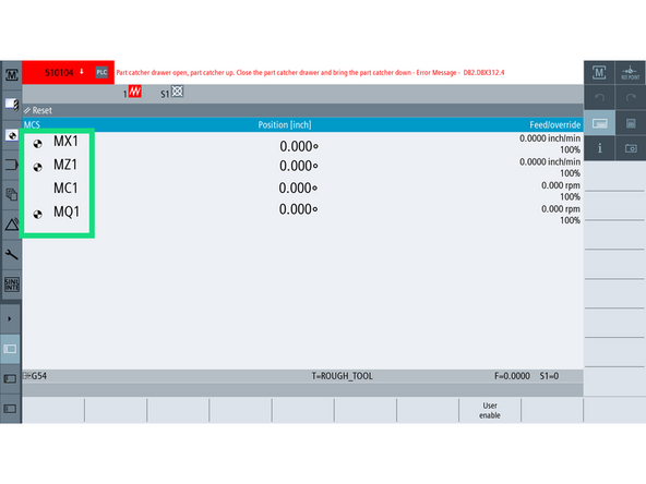
On the [Machine] screen, look for the reference icon beside each axis name: MQ1, MX1 and MZ1.
-
The black and white circle means the axis has a reference. No icon means it does not.
-
All servo axes must show the icon before the machine is operational.
-
The chuck (MC1) does not display a reference icon because it is not a servo axis and does not require referencing.
-
The icon means only that MD34210 = 2, that the control has marked the reference valid. It does not prove the reference is correct.
-
-
-
MD34090 $MA_REFP_MOVE_DIST_CORR. The calibration itself, the offset between machine zero and the encoder zero. The control writes it, not you.
-
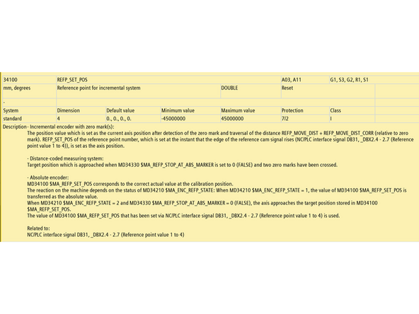
MD34100 $MA_REFP_SET_POS. The coordinate you tell the control the axis is standing at. This is your input.
-
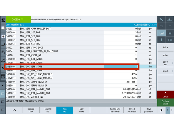
MD34210 $MA_ENC_REFP_STATE. Records whether this axis is referenced. Siemens calls it the adjustment status of the absolute encoder. It holds one of these values:
-
0. Not calibrated. The encoder has no reference to the physical position.
-
1. Calibration enabled. The control will accept MD34100. This is the state you set.
-
2. Calibrated. Written by the control, not by you.
-
With MD34210 = 1, the control transfers MD34100 as the absolute value and computes MD34090 from it. That is the whole mechanism this guide runs on.
-
-
-
The Q axis is the rotational position of the turret.
-
Go to [Machine] → [TSM] → [Select Tool]. Select Tool 1 and press [Cycle Start].
-
Confirm the turret has fully indexed and locked.
-
-
-
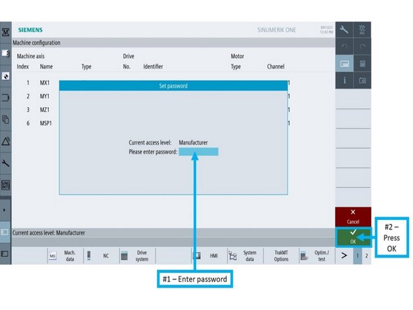
Go to [Setup] → [Mach. Data] → [Axis MD] → [Select Axis] → [MQ1/SERVO] → [OK].
-
Confirm the top right banner reads MQ1 before entering anything.
-
Press [Search], enter 34210, press [OK].
-
Set MD34210[0] = 1.
-
-
-
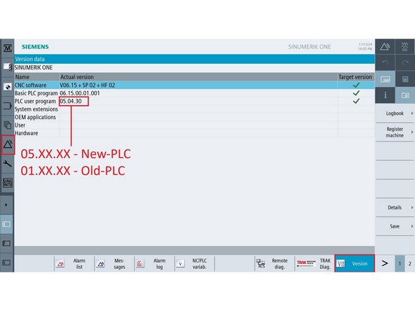
This determines which DB address to use in Step 6.
-
All LTY machines are on New-PLC
-
On the control, go to [Diagnostics] → [Version].
-
Locate the PLC User Program version.
-
If version starts with 05.XX.XX, it is New-PLC.
-
If version starts with 01.XX.XX, it is Old-PLC.
-
-
-
Go to [Diagnostic] → [NC/PLC Variable]
-
In an empty row under Variable, enter the proper bit:
-
Old-PLC → DB34.DBX4.7
-
New-PLC → DB37.DBX4.7
-
Set the Format to [B].
-
On the MCP, press both [JOG] and [REF POINT].
-
Press [Change], enter 1, press [Input] → [OK]. The bit returns to 0 on its own.
-
Confirm the Q axis now shows the reference icon.
-
-
-
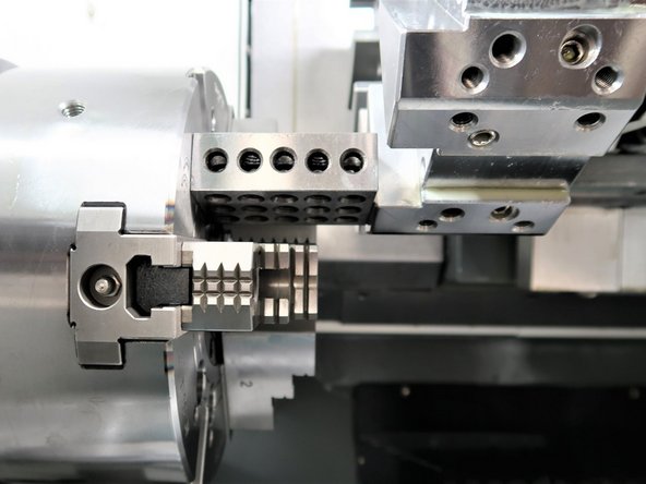
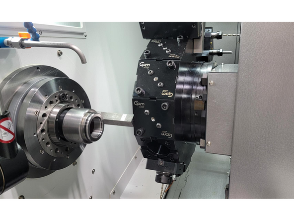
Mount a turret toolholder with a square, machined face in Position 1.
-
For TC820si: Use a boring bar block or standard OD (Outside Diameter) turning tool holder with a flat machined face (e.g., facing or roughing tool block).
-
For TC820LTY: Use a radial live tool holder (facing the spindle) with a square machined face.
-
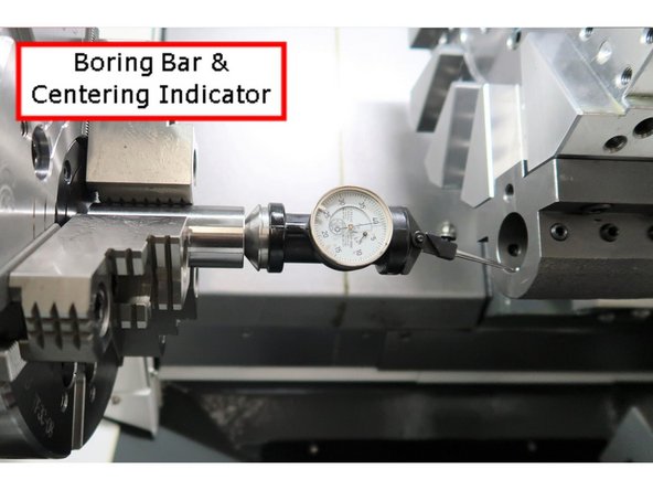
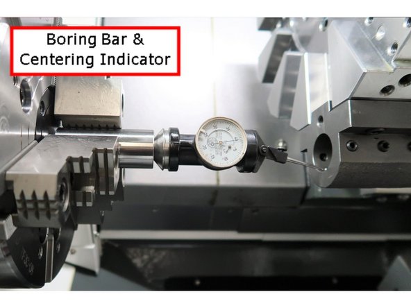
Insert a centering indicator into the spindle
-
Jog X and Z to bring the indicator into contact with the toolholder face.
-
Go to [Machine], press [Act. values MCS] to display Machine Coordinates.
-
Sweep the X-axis back and forth; adjust Z until runout is < 0.001" across +X and −X.
-
This Z-axis position defines the turret’s X0 mechanical centerline.
-
-
-
Go to [Setup] → [Mach. Data] → [Axis MD] → [Select Axis] → [MX1/SERVO] → [OK].
-
Press the [Search] button and enter 34210, then press [OK].
-
On the MCP, turn on [JOG] and [REF. POINT].
-
Set MD34210[0] = 1
-
For TC820 & TC820LTY: Press [+X].
-
Confirm the X-axis shows the reference icon.
-
-
-
Z0 is established by bringing the turret face into contact with a known-height reference object placed against a defined machine surface.
-
The Z-axis reference value is calculated by subtracting the reference object’s height from the machine position at the moment of contact.
-
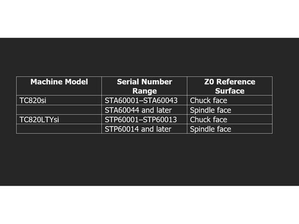
The correct surface to place the reference object depends on the machine model and serial number.
-
TC820si: Serial STA60001–STA60043: Reference from the chuck face.
-
Serial STA60044 and later: Reference from the spindle face.
-
TC820LTYsi Serial STP60001–STP60013: Reference from the chuck face.
-
Serial STP60014 and later: Reference from the spindle face.
-
TC820LTY-Ssi All models reference from the spindle face.
-
-
-
MD34100 tells the control what machine coordinate to assign to the axis during encoder referencing.
-
This value must reflect the height or distance of the physical reference used — such as a 1-2-3 block, 6.000" gauge block, or spindle-to-spindle spacer.
-
Set per axis, MD34100 (Step 11) must be entered before referencing using MD34210 (Step 15) to ensure the encoder aligns with the actual position.
-
-
-
Set MD34100 to match the exact height of the measuring tool or reference stack used when physically referencing the Z1 axis.
-
This value will be assigned as the machine coordinate for Z1 during encoder calibration.
-
TC820 / TC820LTY: Use the block height touched off in Step 12.
-
TC820LTY-S: Use the calculated value from Step 13 & 14: Z1 Reference Value = [Block Height] + A + B
-
Once you have the correct value:
-
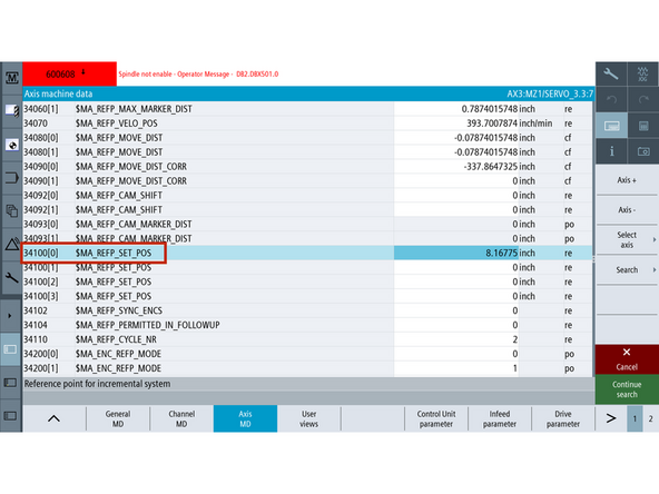
Go to [Setup] → [Mach. Data] → [Axis MD] → [Select Axis] → [MZ1/SERVO].
-
[Search] and enter the value in MD34100.
-
This must be set before referencing the encoder in Step 15.
-
-
-
Remove any tool holder from the turret and clear the spindle face (remove any part or chuck jaws).
-
Place a known-height precision block on the correct surface (see Step 9 for which face to use).
-
Slowly jog the Z-axis until the turret face makes light contact with the block.
-
Ensure there is no visible gap, but do not compress or deflect the block.
-
This contact point is +X.XXX" from actual Z0, where X.XXX = height of your reference block.
-
Go to [Machine], press [Act. values MCS] to switch to machine coordinates.
-
Note the MZ1 machine position while the turret face is in contact with the block — this value will be used to set MD34100 in Step 11.
-
-
-
Place a precision gauge block (6.000" or longer) firmly against the main spindle face.
-
Jog the turret forward until the tool face makes light contact — do not compress the block.
-
Confirm the previously recorded block height, A, and B values from Step 13.
-
Calculate the total: Z1 Reference Value = [Block Height] + A + B.
-
Go to [Machine] → [Actual Values MCS] to display machine coordinates.
-
Record the MZ1 machine coordinate at the moment of contact.
-
This value will be used to set MD34100 in Step 11.
-
-
-
Before continuing, make sure MD34100 has been set correctly in Step 11. This value defines the Z1 position the control will assign during encoder referencing.
-
Go to [Setup] → [Mach. Data] → [Axis MD] → [Select Axis] → [MZ1/SERVO] → [OK].
-
Press the [Search] button and enter 34210, then press [OK].
-
On the MCP, turn on [JOG] and [REF. POINT].
-
Set MD34210[0] = 1
-
For TC820 and TC820LTY: Press [+Z].
-
Confirm the Z-axis shows the reference icon.
-
-
-
Confirm all required axes display the black/white reference icon: Q, X, Z1, and Z2 (for TC820LTY-S).
-
Archive machine state to preserve encoder references.
-
-
Send new archive to TRAK Tech Support or upload to Config Folder
-
-
-

![Press [JOG] and [REF POINT] on the MCP.](https://d3t0tbmlie281e.cloudfront.net/igi/trakmtsupport/awpQxnRLgxCDUrQL.medium)
![On the [Machine] screen, look for the reference icon beside each axis name: MQ1, MX1 and MZ1.](https://d3t0tbmlie281e.cloudfront.net/igi/trakmtsupport/am2exnRLP5CJkajy.medium)

![Go to [Setup] → [Mach. Data] → [Axis MD] → [Select Axis] → [MQ1/SERVO] → [OK].](https://d3t0tbmlie281e.cloudfront.net/igi/trakmtsupport/meuKcncGLBMNj4Jl.medium)
![Go to [Diagnostic] → [NC/PLC Variable]](https://d3t0tbmlie281e.cloudfront.net/igi/trakmtsupport/fyOa35RMPwGZqnMr.medium)
![Go to [Setup] → [Mach. Data] → [Axis MD] → [Select Axis] → [MX1/SERVO] → [OK].](https://d3t0tbmlie281e.cloudfront.net/igi/trakmtsupport/PvAl3nRMTOCxoQUU.medium)
![Press the [Search] button and enter 34210, then press [OK].](https://d3t0tbmlie281e.cloudfront.net/igi/trakmtsupport/kKGI3oRMMOGZqnMr.medium)
![Go to [Setup] → [Mach. Data] → [Axis MD] → [Select Axis] → [MZ1/SERVO] → [OK].](https://d3t0tbmlie281e.cloudfront.net/igi/trakmtsupport/IOFp44RMebGZqnMr.medium)

Team
