Introduction
This procedure re-establishes the absolute encoder reference, and therefore machine zero, on a TC820LTY-Ssi. It covers five servo axes: Q, X, Y, Z1 and Z2.
-
-
This procedure overwrites machine zero on X, Y, Z1 and Z2. The archive is the only way back to the machine's current state.
-
Create a complete machine archive before touching anything.
-
-
-
-
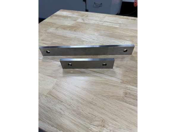
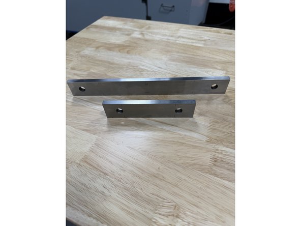
The Z1 and Z2 references use gage blocks.
-
-
-
Call TRAK Service to obtain them. They are a Shars catalog item if the shop needs its own set.
-
-
-
Press [JOG] and [REF POINT] on the MCP.
-
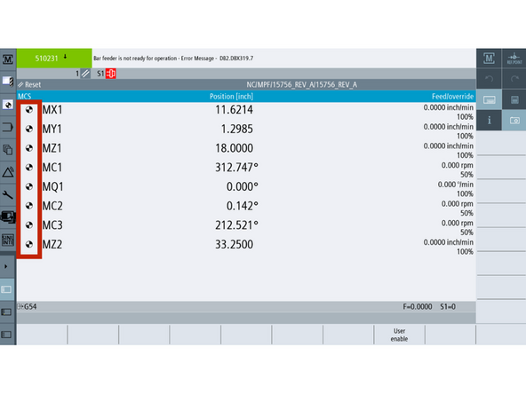
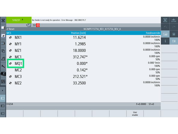
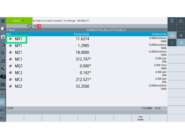
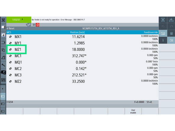
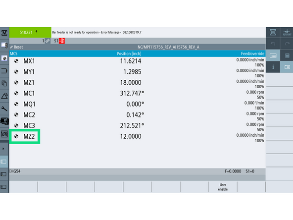
On the [Machine] screen, look for the reference icon beside each axis name: MQ1, MX1, MY1, MZ1 and MZ2.
-
The black and white circle means the axis has a reference. No icon means it does not.
-
All servo axes must show the icon before the machine is operational.
-
MC1 and MC3 are the main and sub spindles. They reference themselves the first time they rotate.
-
MC2 is the driven tool spindle. It references itself the first time it rotates.
-
The icon means only that MD34210 = 2, that the control has marked the reference valid. It does not prove the reference is correct.
-
-
-
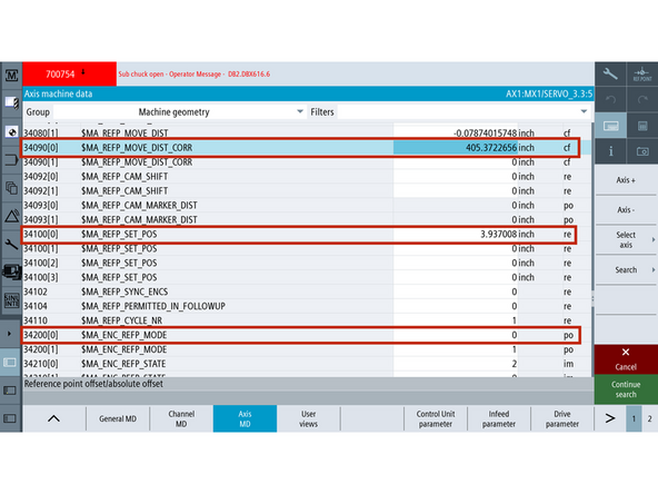
MD34090 $MA_REFP_MOVE_DIST_CORR. The calibration itself, the offset between machine zero and the encoder zero. The control writes it, not you.
-
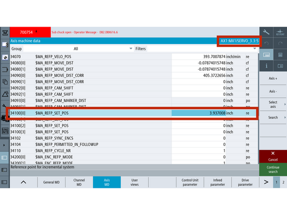
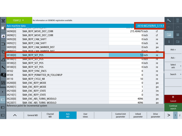
MD34100 $MA_REFP_SET_POS. The coordinate you tell the control the axis is standing at. This is your input.
-
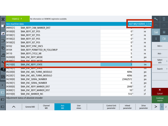
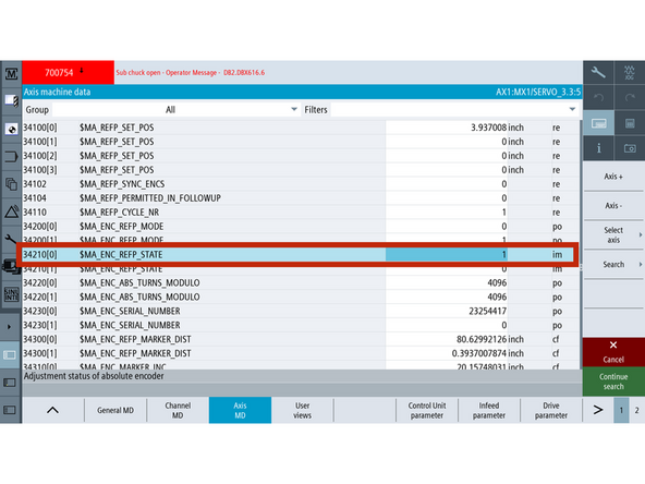
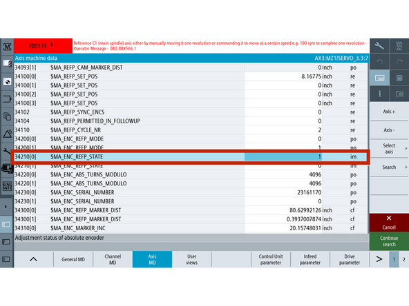
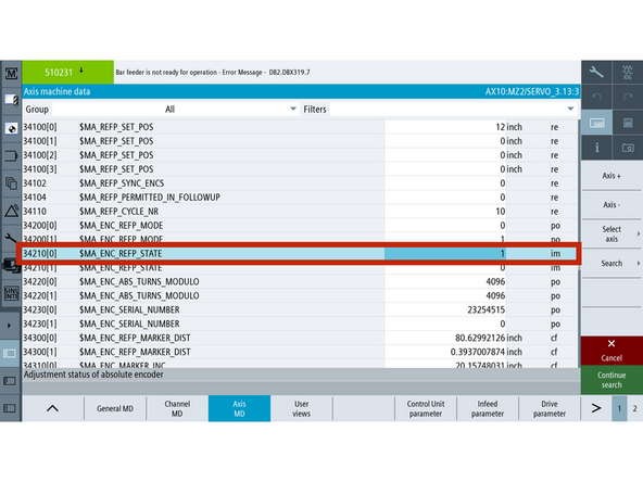
MD34210 $MA_ENC_REFP_STATE. Records whether this axis is referenced. Siemens calls it the adjustment status of the absolute encoder. It holds one of these values:
-
0. Not calibrated. The encoder has no reference to the physical position.
-
1. Calibration enabled. The control will accept MD34100. This is the state you set.
-
2. Calibrated. Written by the control, not by you.
-
With MD34210 = 1, the control transfers MD34100 as the absolute value and computes MD34090 from it. That is the whole mechanism this guide runs on.
-
Because MD34090 is computed from MD34100, a wrong MD34100 produces a wrong machine zero with no alarm and no icon difference.
-
-
-
You only need this step on an axis that is already referenced and has to be re-referenced. If the axis shows no reference icon, skip this step and carry on with that axis.
-
Move the axis to its reference position before you clear the reference.
-
This puts the axis about where it needs to be so the soft limits do not get in the way once the old reference is cleared.
-
Go to [Setup] → [Mach. Data] → [Axis MD] → [Select Axis] and select the axis you are working on. Confirm the top right banner names it before you enter anything.
-
Press [Search], enter 34210, press [OK], and set MD34210[0] = 0.
-
Power cycle the machine.
-
The old reference is now gone. That axis will now accept a new one.
-
-
-
The Q axis is the rotational position of the turret.
-
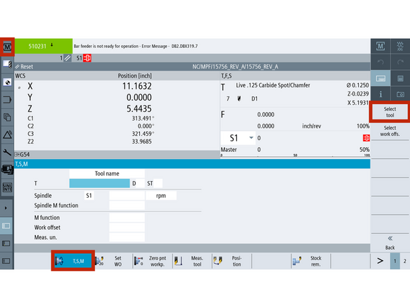
Go to [Machine] → [TSM] → [Select Tool]. Select Tool 1 and press [Cycle Start].
-
Confirm the turret has fully indexed and locked.
-
-
-
Before you start, MD34210[0] must read 0 on MQ1. 0 means the axis has no reference and will accept a new one. If it reads 2, it still holds its old reference and will not take a new one. Go back to Step 6, remove it, and return here.
-
Go to [Setup] → [Mach. Data] → [Axis MD] → [Select Axis] → [MQ1/SERVO] → [OK].
-
Confirm the top right banner reads MQ1 before entering anything.
-
Press [Search], enter 34210, press [OK].
-
Set MD34210[0] = 1.
-
-
-
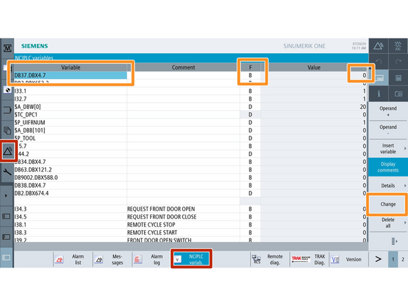
Go to [Diagnostics] → [NC/PLC Variable].
-
In an empty Variable row, enter DB37.DBX4.7
-
Set the Format to [B].
-
On the MCP, press [JOG] and [REF POINT].
-
Press [Change], enter 1 under Value, press [Input] → [OK]. The bit returns to 0 on its own.
-
Confirm the Q axis now shows the reference icon.
-
-
-
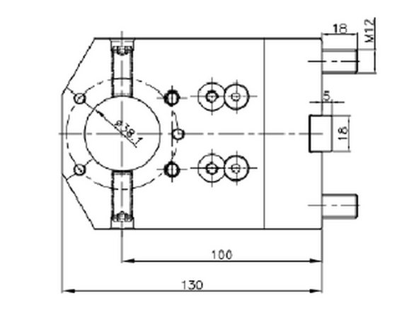
Mount TRAK Part 35723, HOLDER-BORING BAR-1.5"-BMT65, in turret Position 1.
-
Any BMT65 boring bar holder with a 100 mm center height also works.
-
The center height is in the holder designation. 35723 reads B65 BTH 18-38.1 CH100 L120. CH100 is the center height in millimeters.
-
Do not substitute a holder with a different center height. MD34100[0] for X is 100 mm because the holder is. If you do not have a 100 mm holder, stop and call TRAK Service.
-
-
-
X and Y are referenced from one alignment. Do this once and it serves both axes.
-
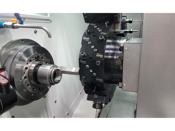
Insert the centering indicator into the chuck.
-
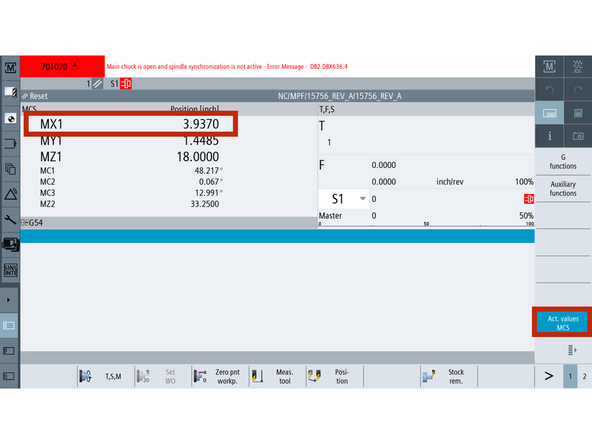
Go to [Machine] and press [Act. values MCS] to display machine coordinates.
-
Bring the centering indicator into contact with the bore of the toolholder.
-
Jog X and Y until the tool center and the spindle center are coincident.
-
Sweep to confirm. Deviation should be under 0.001 in.
-
Do not move X or Y again until both references are set.
-
-
-
Go to [Setup] → [Mach. Data] → [Axis MD] → [Select Axis] → [MX1/SERVO] → [OK].
-
Confirm the top right banner reads MX1. Press [Search], enter 34100, press [OK].
-
On MX1, confirm MD34100[0] = 3.937008, which is exactly 100.000 mm, the center height of holder 35723.
-
Select [MY1/SERVO] and confirm the banner reads MY1. Press [Search], enter 34100, press [OK].
-
On MY1, confirm MD34100[0] = 0.
-
With the bore on the spindle centerline, X is 100 mm (3.937008 in) and Y is 0. X is 100 mm because X zero is the turret face on center and the holder puts the bore 100 mm out from that face. Y is 0 because Y zero is the centerline itself.
-
If either value does not match, correct it before referencing. Whatever sits in MD34100[0] becomes the machine coordinate when you set the reference.
-
-
-
Before you start, MD34210[0] must read 0 on both MX1 and MY1. 0 means the axis has no reference and will accept a new one. If either axis reads 2, it still holds its old reference and will not take a new one. Go back to Step 6, remove it, and return here.
-
Go to [Setup] → [Mach. Data] → [Axis MD] → [Select Axis] → [MX1/SERVO] → [OK].
-
Confirm the banner reads MX1. Press [Search], enter 34210, press [OK]. Set MD34210[0] = 1.
-
Select [MY1/SERVO]. Confirm the banner reads MY1. Press [Search], enter 34210, press [OK]. Set MD34210[0] = 1.
-
On the MCP, turn on [JOG] and [REF. POINT].
-
Press the [X] axis button, then press [+].
-
Press the [Y] axis button, then press [+].
-
Confirm MD34210[0] now reads 2 on both MX1 and MY1.
-
-
-
Confirm X and Y both show the reference icon.
-
Go to [Machine] and press [Act. values MCS].
-
With the tool center still on the spindle center, confirm X reads 3.9370 and Y reads 0.0000.
-
If either reading is wrong, the reference is wrong. Do not continue. Re-check MD34100[0].
-
-
-
Measure the turret, front face to back face. This is W.
-
Measure square to both faces, at or beside turret Position 1.
-
Measure this turret. Do not use W from another machine or a drawing. Every turret gets its own measurement.
-
Write W down.
-
W goes straight into machine zero. Nothing downstream catches an error in it after this step.
-
-
-
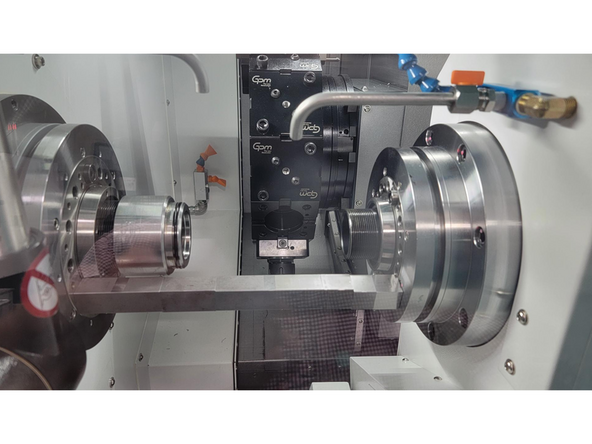
Place the 6.000 in gage block against the main spindle face.
-
Jog the turret forward until the turret front face makes light contact with the block.
-
No visible gap, but do not compress or deflect the block.
-
Leave the axis where it is. Do not move Z until the reference is set.
-
The turret front face is now 6.000 in from the main spindle face.
-
-
-
Calculate 6.000 + W/2. The 6.000 is the block. The W/2 carries the datum from the turret front face back to the turret centerline.
-
Go to [Setup] → [Mach. Data] → [Axis MD] → [Select Axis] → [MZ1/SERVO] → [OK].
-
Confirm the top right banner reads MZ1.
-
Press [Search], enter 34100, press [OK].
-
Enter the calculated value in MD34100[0].
-
-
-
Before you start, MD34210[0] must read 0 on MZ1. 0 means the axis has no reference and will accept a new one. If it reads 2, it still holds its old reference and will not take a new one. Go back to Step 6, remove it, and return here.
-
Still on [MZ1/SERVO], press [Search], enter 34210, press [OK].
-
Set MD34210[0] = 1.
-
On the MCP, turn on [JOG] and [REF. POINT].
-
Press the [Z] axis button, then press [+].
-
MD34210[0] flips to 2 on its own.
-
-
-
Confirm MZ1 now shows the reference icon.
-
Go to [Machine] and press [Act. values MCS].
-
With the turret front face still in contact with the block, confirm MZ1 reads the value you calculated and entered.
-
If it does not, the reference is wrong. Do not continue. Re-check the value you entered in MD34100[0].
-
-
-
Retract the turret fully clear of the working area.
-
Place the 12.000 in gage block between the main spindle and sub spindle faces.
-
Jog the sub spindle forward until it makes light contact with the block.
-
No visible gap, but do not compress or deflect the block.
-
Leave the axis where it is. Do not move Z2 until the reference is set.
-
The sub spindle face is now 12.000 in from the main spindle face. There is no W/2 on this axis: the sub spindle face is the datum itself.
-
-
-
Go to [Setup] → [Mach. Data] → [Axis MD] → [Select Axis] → [MZ2/SERVO] → [OK].
-
Confirm the top right banner reads MZ2.
-
Press [Search], enter 34100, press [OK].
-
Enter 12.000 in MD34100[0].
-
-
-
Before you start, MD34210[0] must read 0 on MZ2. 0 means the axis has no reference and will accept a new one. If it reads 2, it still holds its old reference and will not take a new one. Go back to Step 6, remove it, and return here.
-
Still on [MZ2/SERVO], press [Search], enter 34210, press [OK].
-
Set MD34210[0] = 1.
-
On the MCP, turn on [JOG] and [REF. POINT].
-
Press the [Z2] axis button, then press [+].
-
MD34210[0] flips to 2 on its own.
-
-
-
Confirm MZ2 now shows the reference icon.
-
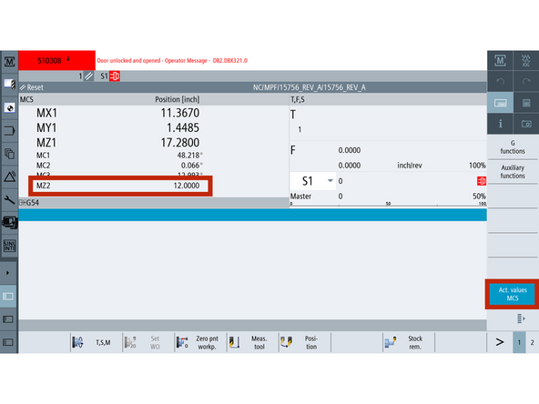
Go to [Machine] and press [Act. values MCS].
-
With the sub spindle still in contact with the block, confirm MZ2 reads 12.000.
-
If it does not, the reference is wrong. Do not continue. Re-check MD34100[0].
-
-
-
If machine zero has moved, anything calibrated against machine position is now wrong.
-
Recalibrate the tool setter. Probe calibration is machine position based.
-
-
-
-
Create a complete machine archive now that the references are set.
-
-
Send new archive to TRAK Tech Support or upload to Config Folder
-
-



Team
