-
-
These charts are labeled to include the wiring connections for the Hydraulic 8 Tool Turret for the TRAK TRL 30120RX. The Part Number: 29103-16 document had also been included at the end of this guide.
-
-
-
These images refer to the Computer Module Port Designations within the electrical cabinet for the TRAK TRL 30120RX.
-
The Computer Module port diagram is also included within the Part Number: 29100-6 document, which is included at the bottom of this guide.
-
-
-
Turn off the power to machine. All work to be performed when powered off, with the exception of the checking phase, motor rotation, and pressure adjustments.
-
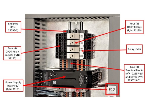
Remove the End Stop (P/N: 23095-1) that is placed on top of F12 on the electrical cabinet, and install the Power Supply (P/N: 31191) over F12. Make sure that the Power Supply is installed horizontally, and that the side with the label is facing upward. Lock it in the DIN Rail.
-
With the label facing up, the Power Input will be on the right side of the Power Supply, and the 24V Output will be on the left side.
-
Assemble the four Terminal Blocks (P/N: 22557-10) and the Terminal Block Cover (P/N: 22557-9-C1). Snap each terminal block on DIN Rail, with exposed contacts facing up. Install cover on top of the last terminal to isolate the contacts.
-
Install the four DPDT Relay Sockets (P/N: 31190) on the DIN Rail over the Terminal Blocks. Next, install each of the four DPDT Relays (P/N: 31189) on the Relay Sockets; make sure to sure lock them in from the right side of each socket.
-
Place the End Stop back into the electrical cabinet on top of the four DPDT Relays.
-
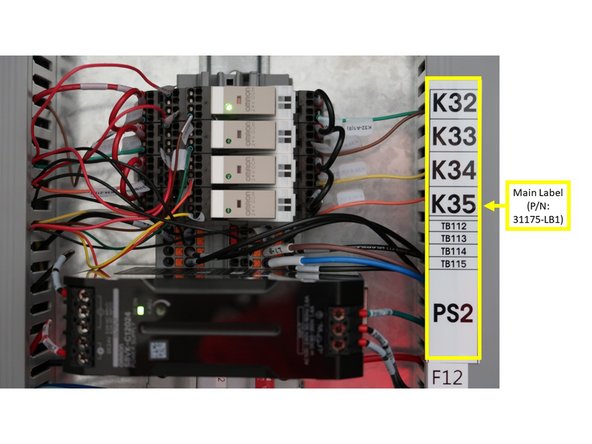
Install Main Label (P/N: 31175-LB1; as shown on the second left image) in order to designate electrical cabinet locations for the relays and the terminals.
-
Replace F10 and F11 fuses with two 4A Fuses (P/N: 23152-4). Return the 2A fuses to stock.
-
-
-
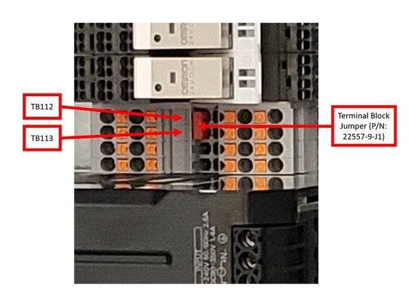
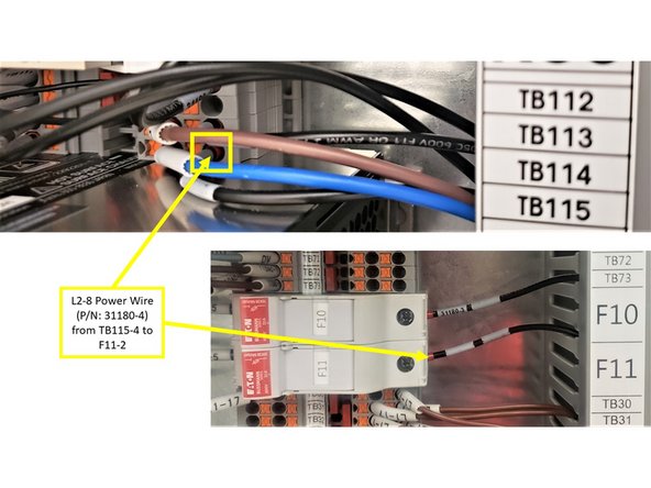
Install the Terminal Block Jumper (P/N: 22557-9-J1) vertically across TB112 and TB113 as shown on the first image on the left.
-
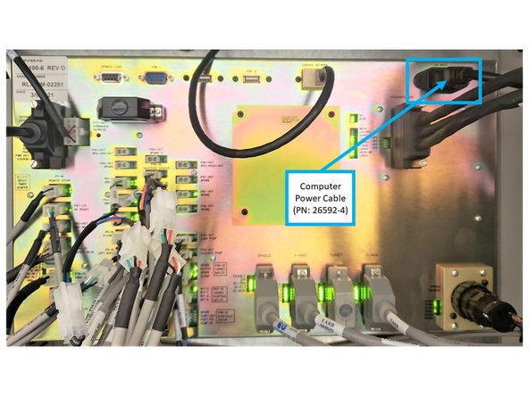
The Computer Power Cable (P/N: 26592-4) will come pre-installed on the TRAK 30120RX (see second image on the left).
-
One end of the Computer Power Cable is connected to the AC Power Input receptacle on the computer module.
-
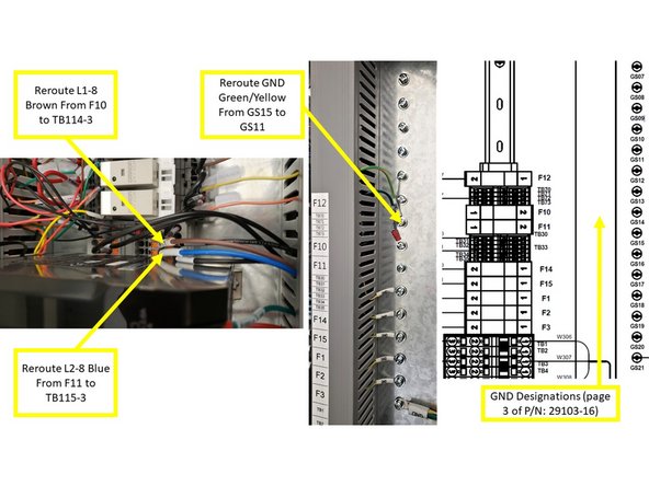
The opposite end has Brown, Blue, and Green/Yellow (Ground) Wires that are already connected to F10, F11, and GND. The routing to the colored wires must be changed to the following:
-
Reroute the Computer Power L1-8 Brown wire from the F10 fuse box to the TB114-3 terminal.
-
Reroute the Computer Power L2-8 Blue Wire from the F11 fuse box to the TB115-3 terminal.
-
Reroute the Computer Power Ground Green/Yellow Wire from GS15 to GS11.
-
Please refer to page 3 of P/N: 29103-16 document for the GND designations within the electrical cabinet. This document is also provided at the bottom of this guide.
-
-
-
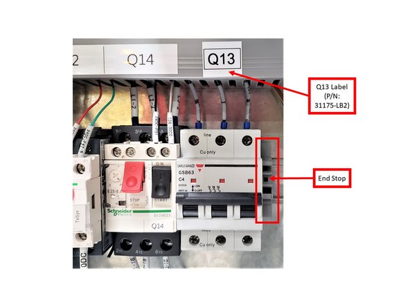
Place the Q13 Label (P/N: 31175-LB2) on the designated area next to Q14, and remove the End Stop (P/N: 23095-1) that is also placed next to Q14 as well.
-
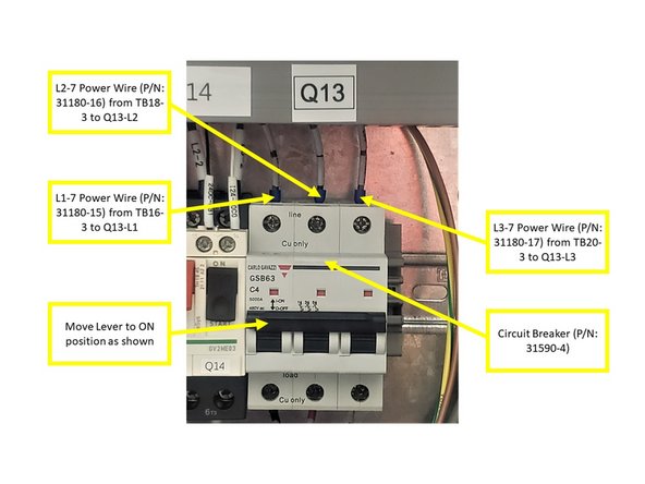
Install the Circuit Breaker (P/N: 31590-4) under Q13 label, and put back the End Stop to the right of the Circuit Breaker.
-
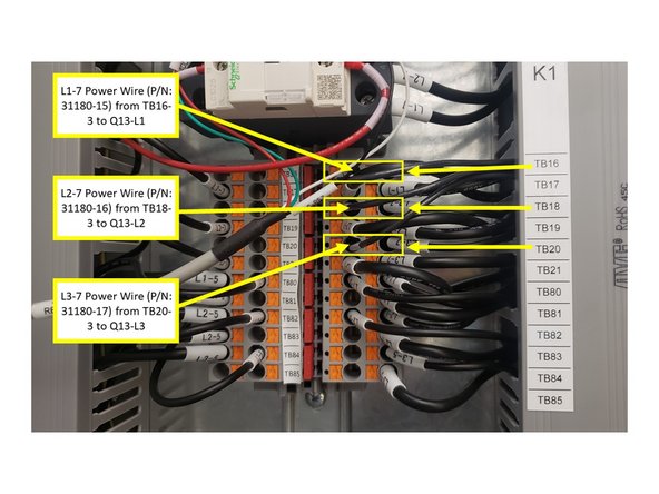
Install the following Power Wires from the Terminals, through the Wire Way, and into the Circuit Breaker (please see second and third images on the left):
-
Install L1-7 Power Wire (P/N: 31180-15) from the TB16-3 Terminal to Q13-L1 of the Circuit Breaker.
-
Install L2-7 Power Wire (P/N: 31180-16) from TB18-3 to Q13-L2.
-
Install L3-7 Power Wire (P/N: 31180-17) from TB20-3 to Q13-L3.
-
Move lever to ON on Circuit Breaker, as shown on the third image on the left.
-
-
-
Install Wires from the Terminals, through the Wire Way, and into the F10 and F11 Fuse holders (please see image):
-
Install L1-8 Wire (P/N: 31180-3) from the TB114-4 Terminal to F10-2 Fuse holder as shown.
-
Install L2-8 Wire (P/N: 31180-4) from TB115-4 to F11-2 as shown.
-
-
-
Please refer to the left image for a diagram of the Terminal Arrangement/Internal Connections for the Relay Socket Terminals.
-
The Part Number 31190 document is also included at the bottom of this guide for your reference.
-
-
-
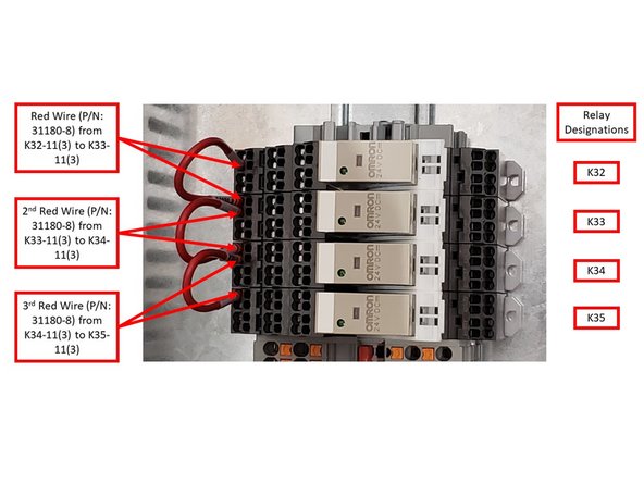
Install three (3) Red Wires (P/N: 31180-8) on the Relay Socket Terminals (please see image):
-
Use a screwdriver to lever the spring within the Relay Socket Terminal in order install the wires.
-
Install the 1st Red Wire from the bottom left K32-11(3) to the top left K33-11(3) Relay Sockets.
-
Install the 2nd Red Wire from the bottom left K33-11(3) to the top left K34-11(3) Relay Sockets.
-
Install the 3rd Power from the bottom left K34-11(3) to the top left K35-11(3) Relay Sockets.
-
-
-
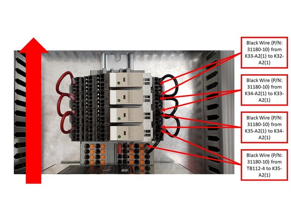
Install four (4) Black Wires (P/N: 31180-10) on Relay Sockets as follows (please see image):
-
Start from the bottom highlighted connection at the TB112-4 Terminal, and work your way up the Relay Sockets.
-
Install the 1st Black Wire from the TB112-4 Terminal to the bottom right K35-A2(1) Relay Socket.
-
Install the 2nd Black Wire from the top right K35-A2(1) to the bottom right K34-A2(1) Relay Sockets.
-
Install the 3rd Black Wire from the top right K34-A2(1) to the bottom right K33-A2(1) Relay Sockets.
-
Install the 4th Black Wire from the top right K33-A2(1) to the bottom right K32-A2(1) Relay Sockets.
-
-
-
Install Green GND Wire (P/N: 31180-5) from PS-GND on the right side of the Power Supply, through the Wire Way, and into GS15 (as shown on the first image on the left).
-
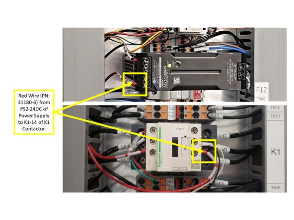
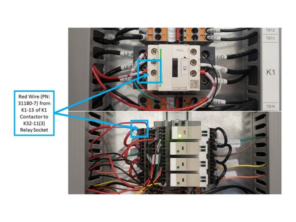
Install Red Wire (P/N: 31180-6) from PS2-24DC on the left side of the Power Supply, through the Wire Way, and into K1-14 on the right side of the K1 Contactor in the electrical cabinet (as shown on the second image on the left).
-
Install Red Wire (P/N: 31180-7) from K1-13 on the left side of the K1 Contactor, through the Wire Way, and into the top left K32-11(3) Relay Socket (as shown on the third image on the left).
-
This Red Wire is installed above the Red Wire (P/N: 31180-8; mentioned in Step 6 of this guide), which is on the bottom left K32-11(3) Relay Socket.
-
-
-
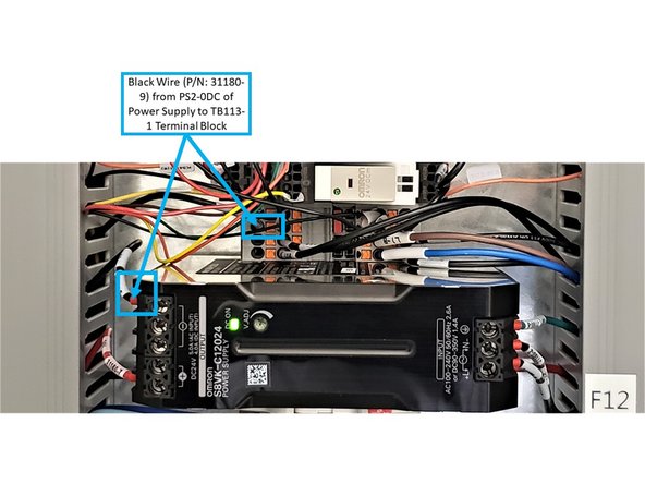
Install Black Wire (P/N: 31180-9) from PS2-0DC on the left side of the Power Supply, through the Wire Way, and into the TB113-1 Terminal (as shown on the first image on the left).
-
Install Black Wire (P/N: 31180-1) from the TB114-2 Terminal, through the Wire Way, and into PS-L on the right side of the Power Supply.
-
Install Black Wire (P/N: 31180-2) from the TB115-2 Terminal, through the Wire Way, and into PS-N on the right side of the Power Supply.
-
-
-
Install the following wires on the Relay Sockets:
-
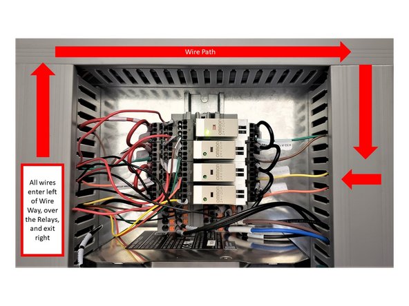
Insert all of the following wires from the Relays to the left side of the Wire Way first, then over and around the Relays, and exit through the right side of the Wire Way.
-
Install the Brown Wire (P/N: 31180-11) from the bottom left K32-21(6) Relay Socket, through the Wire Way, and into the bottom right K33-A1(8) Relay Socket.
-
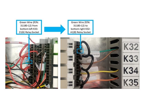
Install the Green Wire (P/N: 31180-12) from the bottom left K33-21(6) Relay Socket, through the Wire Way, and into the bottom right K32-A1(8) Relay Socket.
-
-
-
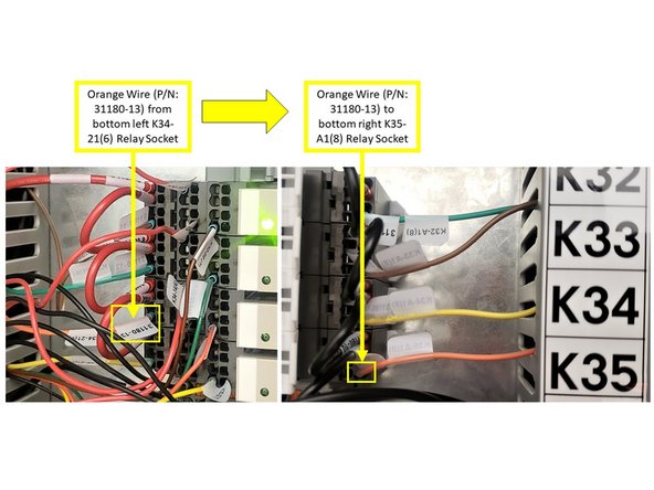
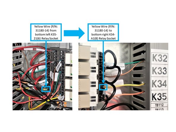
Install the following wires on the Relay Sockets:
-
Insert all of the following wires from the Relays to the left side of the Wire Way first, then over and around the Relays, and exit through the right side of the Wire Way.
-
Install the Orange Wire (P/N: 31180-13) from the bottom left K34-21(6) Relay Socket, through the Wire Way, and into the bottom right K35-A1(8) Relay Socket.
-
Install the Yellow Wire (P/N: 31180-14) from the bottom left K35-21(6) Relay Socket, through the Wire Way, and into the bottom right K34-A1(8) Relay Socket.
-
-
-
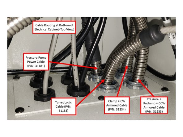
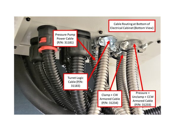
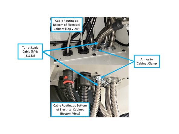
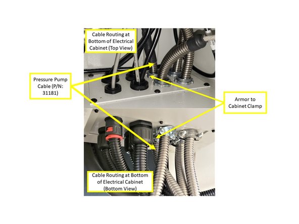
Remove rubber grommets at the bottom of the electrical cabinet in order to mount the following cables:
-
Pressure Pump Power Cable (P/N: 31181)
-
Turret Logic Cable (P/N: 31183)
-
Clamp + CW Armored Cable (P/N: 31234)
-
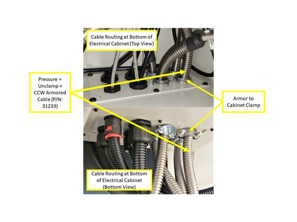
Pressure + Unclamp + CCW Armored Cable (P/N: 31233)
-
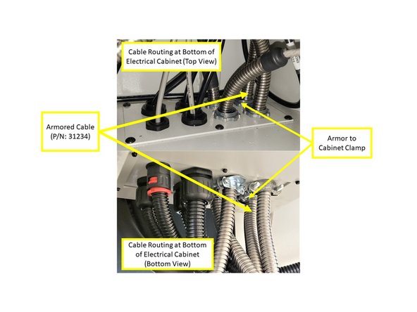
Refer to both images on the left for top and bottom views of the cable routing at the bottom of the electrical cabinet.
-
Instructions on installing the above cables are provided on later steps.
-
-
-
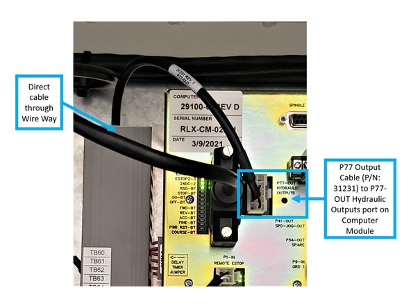
Install the P77 Output Cable (P/N: 31231) from the P77-OUT Hydraulic Outputs port of the computer module to the K32 to K35 Relays and the TB112-3 Terminal in the electrical cabinet. See first image on the left for a diagram of the P77 Output Cable.
-
Install the Connector end of the P77 Output Cable on the P77-OUT Hydraulic Outputs port on the computer module, and direct the opposite end of the cable through the Wire Way as indicated on the second image on the left.
-
Directed from the Wire Way, install the five (5) wires of the P77 Output Cable to the Relays and TB112-3 Terminal via the following designations:
-
Install the Brown Wire to the bottom left K32-22(7) Relay.
-
Install the Green Wire to the bottom left K33-22(7) Relay.
-
Install the Orange Wire to the bottom left K34-22(7) Relay.
-
Install the Yellow Wire to the bottom left K35-22(7) Relay.
-
Install the Black Wire to the TB112-3 Terminal Block.
-
-
-
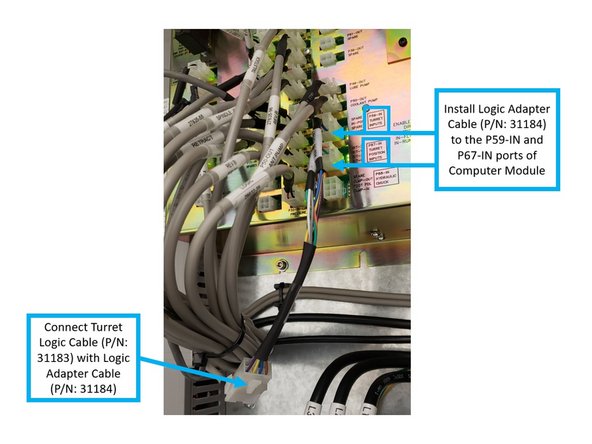
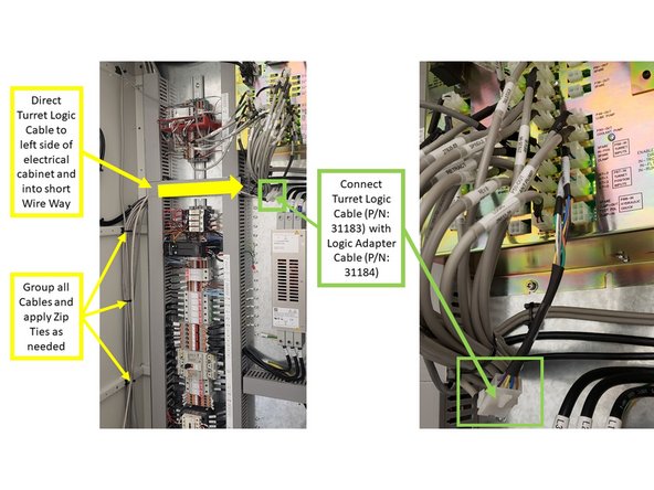
Install the Turret Logic Cable (P/N: 31183) with the Logic Adapter Cable (P/N: 31184) on the P59-IN and P67-IN ports of the electrical cabinet, and install its opposite end to the Sensor Housing on Turret. See first image on the left for a diagram of the Turret Logic Cable.
-
Install the Logic Adapter Cable to the P59-IN and P67-IN ports of the computer module.
-
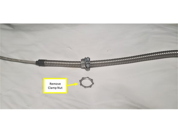
Next, connect the Logic Adapter Cable with the Turret Logic Cable itself. Begin by removing Cable Clamp Nut from the Turret Logic Cable.
-
-
-
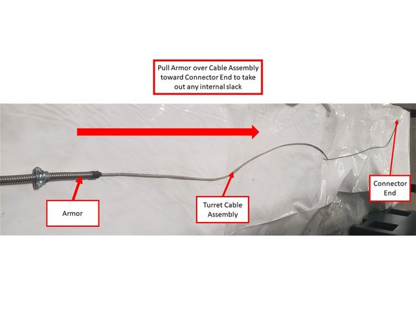
Place the Turret Logic Cable on a flat surface. Pull the moveable end of the Armor over the Cable Assembly toward the Connector End until it is fully extended. This is to take out any internal slack within the Armor.
-
Make sure that the Armor is fully extended over the Cable Assembly; any internal slack may cause future wiring issues.
-
Route the Cable Assy into the electrical cabinet through the hole described in Step 14. Reinstall Cable Clamp Nut, and tighten.
-
Route the cable on bottom of cabinet to left side of the electrical cabinet, away from the power wires, and into the short wire way that leads to the computer module inputs.
-
Next, connect the Logic Adapter Cable to the Turret Logic Cable itself.
-
-
-
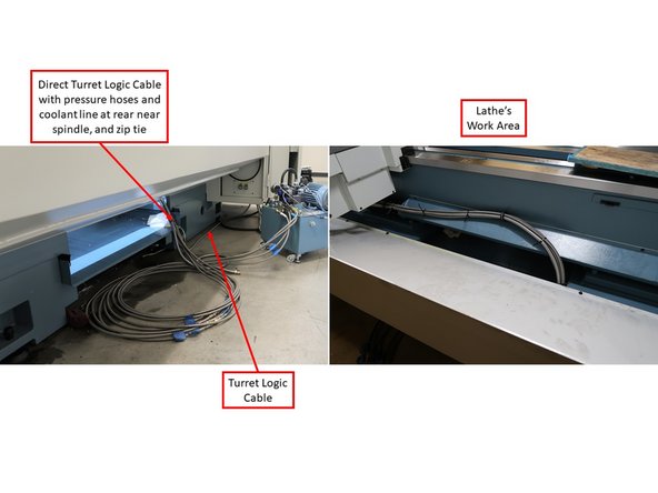
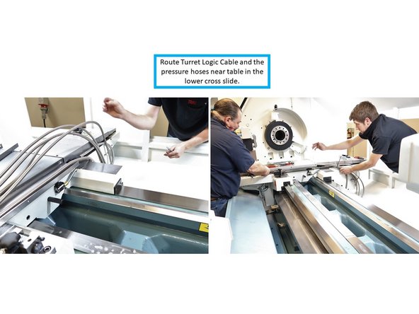
From underneath the electrical cabinet, direct the Turret Logic Cable, along with the pressure hoses, into the lathe's work area.
-
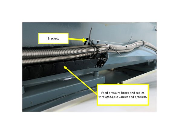
The Cable Carrier helps organize the Turret Logic Cable and pressure hoses, as well as keeps them in position as the table travels back and forth. There are brackets every 18" or so to keep the Turret Logic Cable and pressure hoses in position. Feed the Turret Logic Cable and pressure hoses through each bracket.
-
Tip: Extend the table toward the far end, and route the Turret Logic Cable and pressure hoses through the brackets. Then move the table closer to the spindle, and the cable and pressure hoses will make the turn. It is difficult to route the cable and pressure hoses by hand through the brackets while the Cable Carrier makes its 180 degree turn.
-
Route the Turret Logic Cable and pressure hoses near the table in the lower cross slide. The Turret Logic Cable and pressure hoses will fit in the cross slide with the top bolted in place. Use rubber hose clamps to control the Turret Logic Cable and pressure hoses from the Cable Carrier up to the table.
-
Please refer to the Big Lathe Turret - Route Hydraulic Hoses Dozuki Guide under 07 - Product Support - Options for more detailed information on how to properly route and install the Turret Logic Cable and the pressure hoses together to the Hydraulic 8-Tool Turret and the TRAK TRL 30120RX Lathe itself.
-
-
-
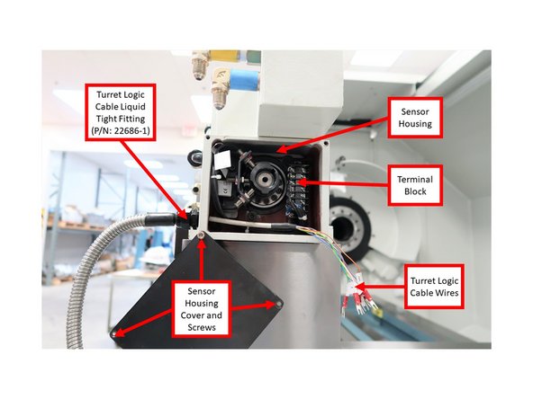
On the Turret itself, remove the four (4) screws and the cover on the Sensor Housing. Install the Turret Logic Cable through its Liquid Tight Fitting (P/N: 22686-1) on the Sensor Housing as shown on the first image on the left.
-
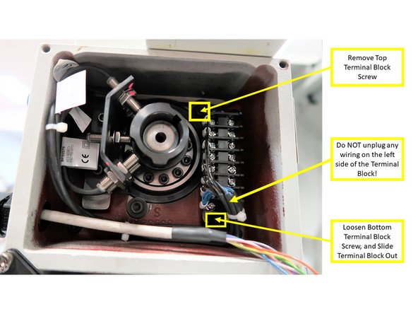
Once the Turret Logic Cable had been installed on the Sensor Housing, begin installing the Turret Logic Cable colored wires to the Sensor Housing Terminal Block. In order to assist with the wiring process, you may remove the top Terminal Block screw, loosen the bottom screw, and carefully slide the Terminal Block out of the Sensor Housing.
-
Do NOT unplug any of the wiring that is pre-installed on the left side of the Terminal Block!
-
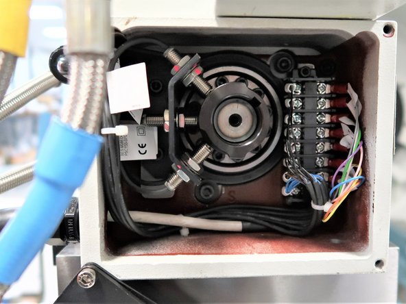
Please follow the Interconnections Chart that is shown on the third image on the left in order to install the Turret Logic Cable Wires to the right side of the Terminal Block.
-
-
-
Once the Turret Logic Cable wires had been properly installed on the Sensor Housing Terminal Block, place the Terminal Block back inside the Sensor Housing by securing both top and bottom screws of the Terminal Block to their designated places. Place the Cover back on the Sensor Housing, and secure its four screws back on each of its corners.
-
-
-
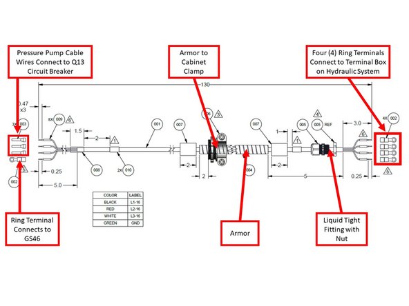
Install the Pressure Pump Cable (P/N: 31233) from the Q13 Circuit Breaker to the Terminal Box on the Pump Housing on the Hydraulic System. See first image on the left for a diagram of the Pressure Pump Cable.
-
Remove the Clamp Nut, and guide the cable into cabinet through its designated hole, as shown in the second image on the left. Reinstall the clamp nut and tighten.
-
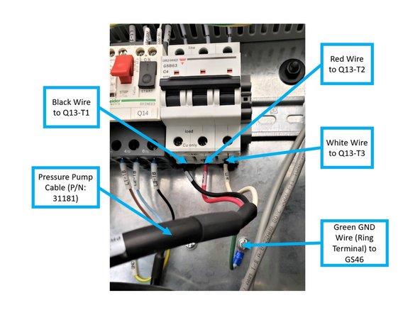
Install the Pressure Pump Cable's three (3) Power Wires and Ring Terminal to the Q13 Circuit Breaker via the following designations (please see second image on the left):
-
Install the Black Wire to Q13-T1.
-
Install the Red Wire to Q13-T2.
-
Install the White Wire to Q13-T3.
-
Install the Green GND Wire (Ring Terminal) to GS46.
-
-
-
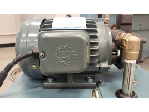
Remove the Cover and four (4) screws inside the Terminal Box on the Hydraulic System. Rotate the entire Terminal Box as shown on the first image on the left; it must be rotated so that the hole for the Liquid Tight Fitting with Nut (P/N: 31696-1) is on the left side, and the terminals are horizontal. Once rotated, place back the four screws.
-
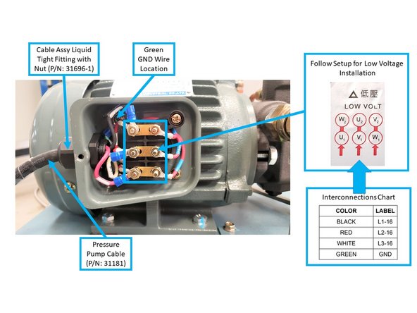
Install the Pressure Pump Cable to the Terminal Box along with the Liquid Tight Fitting with Nut (Part Number 31696-1), as shown on the second image on the left.
-
There will be wires coming from within the terminal box with the following labels: U1, U2, V1, V2, W1, and W2, along with label instructions for both high and low voltage installation. Per the second image on the left, follow the instructions for low voltage installation:
-
Top row: combine the black wire (L1-16) with the U1 wire on the left, and set the W2 wire on the right.
-
Second row: combine the red wire (L2-16) with the V1 wire on the left, and set the U2 wire on the right.
-
Bottom row: combine the white wire (L3-16) and the W1 wire on the left, and set the V2 wire on the right.
-
Install the Green GND Wire to its location on the top left screw inside the terminal box, as shown on the second image on the left.
-
Once the Pressure Pump Cable is properly installed inside the Terminal Box, secure the screw and cover back on the Terminal Box on the Hydraulic System.
-
-
-
Remove the Cable Clamp Nut from the Armored Cable (P/N: 31234).
-
Route the Cable Assembly into electrical cabinet through the hole described in Step 14. Reinstall Cable Clamp Nut, and tighten.
-
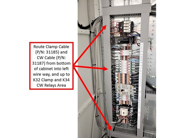
Route both cables of Assy P/N: 31234 (Clamp Cable P/N: 31185 and CW Cable: 31187) on bottom of cabinet into left wire way, and up to K32 Clamp and K34 CW Relays area.
-
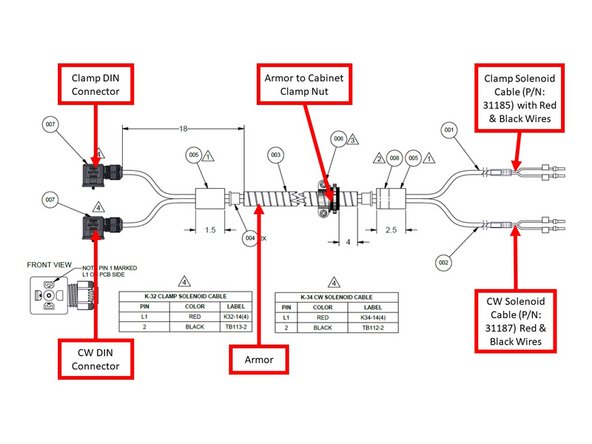
See second image on the left for a diagram of the Armored Cable (P/N: 31234), and the third image for the wire way routing in electrical cabinet.
-
-
-
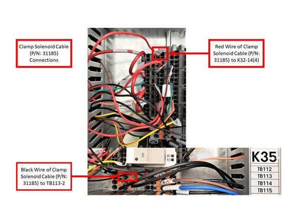
Begin by installing the Clamp and CW Solenoid Cables from the left wire way to the following Relay Areas in the electrical cabinet:
-
Connect the Red Wire of the Clamp Solenoid Cable (P/N: 31185) to K32-14(4) Relay Socket.
-
Install the Black Wire of the Clamp Solenoid Cable on the TB113-2 Terminal.
-
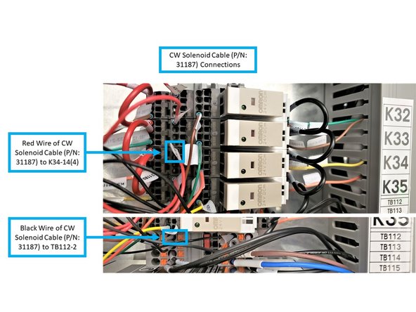
Connect the Red Wire of the CW Solenoid Cable (P/N: 31187) to K34-14(4) Relay Socket.
-
Install the Black Wire of the CW Solenoid Cable on the TB112-2 Terminal.
-
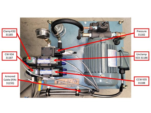
Connect DIN Connectors to corresponding pressure valves according to chart/picture.
-
-
-
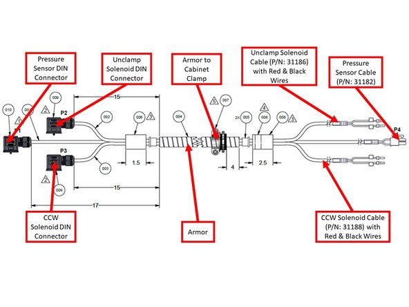
Install one end of the Pressure + Unclamp + CCW Armored Cable (P/N: 31233) to the electrical cabinet, and the other end to both the Solenoid Valve Body and Sensor Body on the Hydraulic System. See first image on the left for a diagram of the Pressure + Unclamp + CCW Armored Cable.
-
Remove Cable Clamp Nut, and route the Cable Assy into the electrical cabinet through the Armored Cable's designated hole as described on Step 14 of this guide. Reinstall the Clamp Nut and tighten.
-
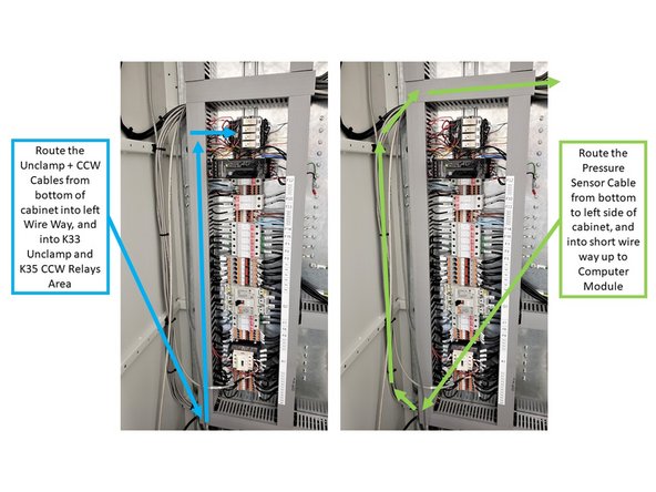
Route the Unclamp and CCW cables from the bottom of the cabinet into the left wire way, and up to K33 Unclamp and K35 CCW Relays Area, as shown on the third image on the left.
-
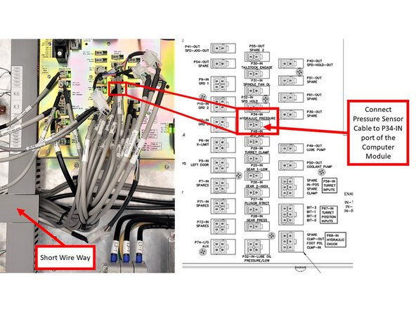
Route the Pressure Sensor Cable on the bottom of cabinet and to the left side, and into the short wire way that leads up to the Computer Module (also shown on the third image on the left).
-
-
-
From the short Wire Way, connect the Pressure Sensor Cable to the P34-IN port of the computer module within the electrical cabinet (as shown on the first image on the left).
-
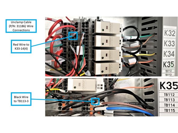
Connect the following colored wires of the Unclamp Cable (P/N: 31186) to the following locations in the electrical cabinet:
-
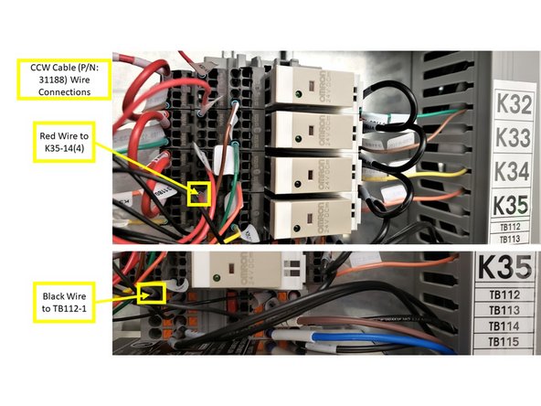
From the Left Wire Way, connect the Red Wire to K33-14(4), as shown on the second image on the left.
-
From the Left Wire Way, connect the Black Wire to TB113-3 (also shown on the second image on the left).
-
Connect the following colored wires of the CCW Cable (P/N: 31188) to the following locations in the electrical cabinet:
-
From the Left Wire Way, connect the Red Wire to K35-14(4), as shown on the third image on the left.
-
From the Left Wire Way, connect the Black Wire to TB112-1 (also shown on the third image on the left).
-
-
-
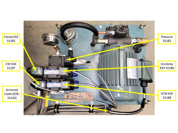
Install both DIN Connectors of the Unclamp and CCW Cables on their designated locations on the Solenoid Valve Body of the Hydraulic System itself (as shown on the first image on the left).
-
In addition, install the DIN Connector of the Pressure Sensor Cable on the Sensor Body of the Hydraulic System itself (also shown on the first image on the left).
-
-
-
First concern is safety. Tool holders are heavy and may need two people to lift from lathe. This example does not have eye hooks to be able to lift with as hoist; however, a fixture could be made to slide in the top to lift with a hoist if needed.
-
Mill should not be operational while removing heavy equipment.
-
If the tool holder has hose connections, make sure they are disconnected from the supply source before removal.
-
Unbolt tool holder from cross slide. Remove, being careful not to damage ground surface on bottom.
-
-
-
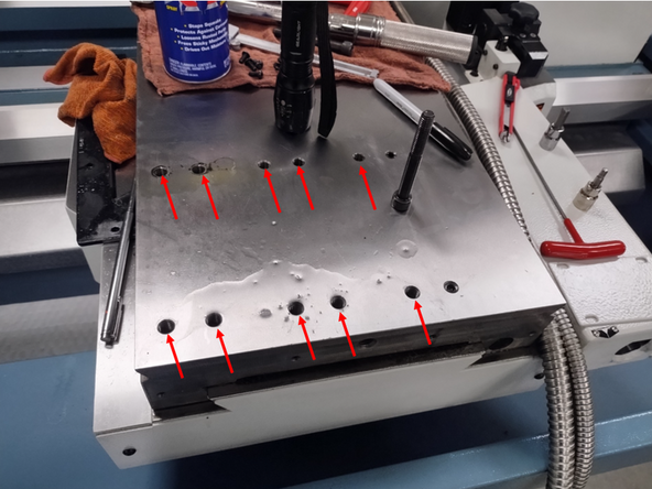
Check threaded holes prior to turret base installation
-
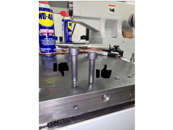
Use M10X75 bolts to verify hole quality. Bolt should be able to go down to shank relatively smoothly. If bolt cannot thread all the way down, clean up holes/add thread using M10 tap.
-
-
-
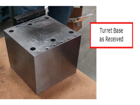
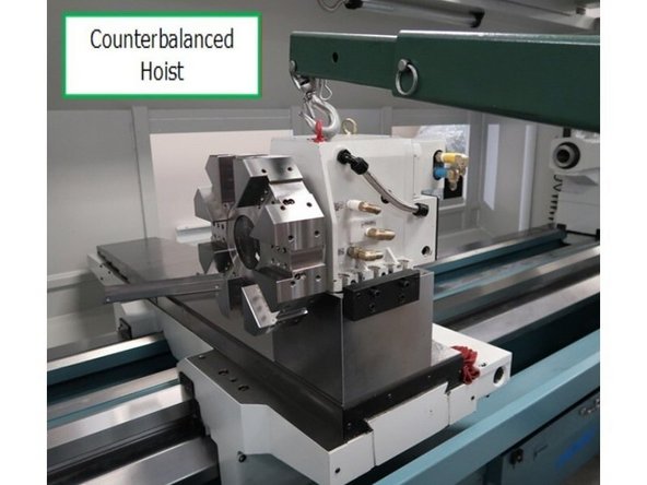
Warning: heavy object, lifting base requires a hoist. Care should be taken to move it around. It can be flipped over to another side but should not be lifted by a person with a crane.
-
Machine shop will grind and provide correct base during final assembly and alignment. Prepare a clean surface for base installation. Flip base as needed on clean surface to inspect all sides for dirt or imperfections. Clean with cloth or use fine oil stone as need for a smooth snag free surface all over.
-
Cleaning fine burrs around the holes to verify a smooth surface on all sides of the base.
-
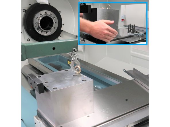
Prepare smoothed table with plenty of oil to allow base to slide easily when placed on base. Use hoist to set base on the table. Carefully slide base adding oil as needed. Align holes in base with holes in table. Start all of the M10-80 bolts before tightening to 40 ft/lbs.
-
-
-
Using a counterbalance hoist, lift turret out of crate or where stored to carefully align and place it in position.
-
The design of the turret and or its connections will prevent access to some of the bolts. Ten M10-45 bolts are used for the turret, but likely only 9 will be accessible. Start all of the accessible bolts, and torque to 30 ft/lbs.
-
-
-
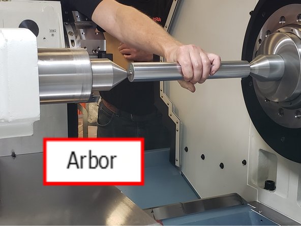
TRAK has a documented diameter arbor used to place between two dead centers to easily measure the height of the center line of lathe. Install a dead center in the headstock and another in the tailstock.
-
Carefully install the arbor between the two dead centers.The diameter of the arbor is 40 mm, so the centerline of that arbor is the theoretical centerline.
-
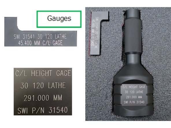
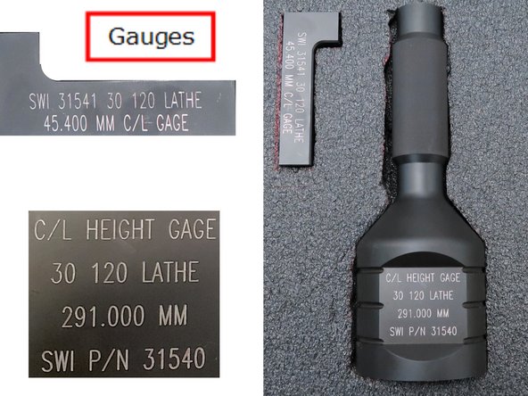
Second piece of test equipment is a set of standards. There is a 291mm height gauge as well as a 45.4 mm turret centerline gauge.
-
-
-
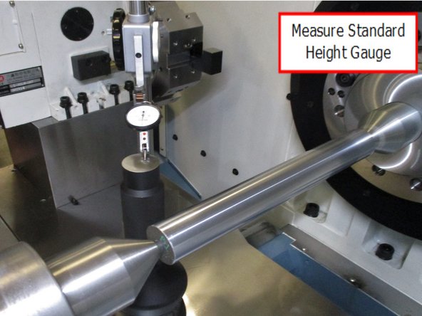
Carefully slide over the height gauge and zero on the standard in the turret.
-
Using height gauge, measure the top of the arbor.
-
Centerline height of the lathe is found from the difference in these two measurements, higher or lower.
-
Centerline height gauge standard is 291mm to compensate for 20mm radius of arbor. Height of spindle is indicated height of arbor - 20mm. This should be 10.6693” +/- .0138”. (271mm +/- .35mm).
-
-
-
Standards: you will use the Centerline Gauge for this calculation. Height Gauge is used during machine inspection to measure the centerline height. We need that measurement for this calculation.
-
Mount the gauge into the turret. Height of machined flat spot of the gauge is 20 mm above the centerline of the cutting edge on the turret.
-
-
-
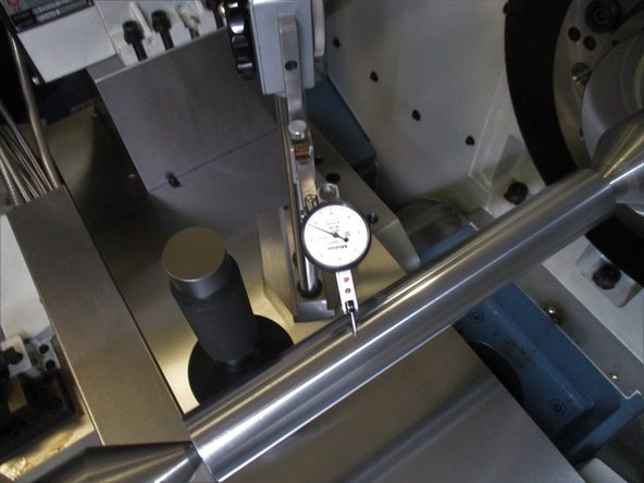
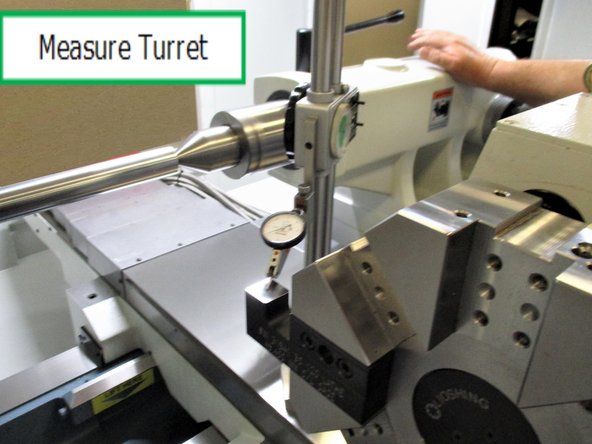
Zero out the dial gauge on the standard height gauge.
-
Carefully slide over the dial indicator to measure the height of the turret.
-
The difference from the height gauge, the centerline gauge, and the turret height will give you the number needed for the base. This part is ground to that specific dimension at TRAK. When the needed base height is calculated, request TRAK Mach Shop to grind the base, urgency based upon the lathe delivery date.
-
Example:
-
Spindle Centerline - Turret Centerline = Turret base height
-
Turret centerline will come from the documentation sheet. We can double check it with the factory setup turret base. We should get a measurement of +/-.05mm (+/-.002”).
-
290.000 Gauge Standard - 20 C/L Standard - 80 Turret = number needed for base (millimeters)
-
The 8 Tool Turret = 80 number is supplied by the manufacturer, rounded here to show theory, actual number is much more accurate.
-
-
-
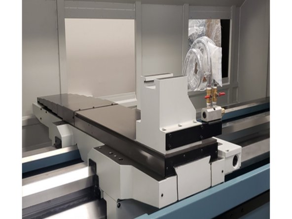
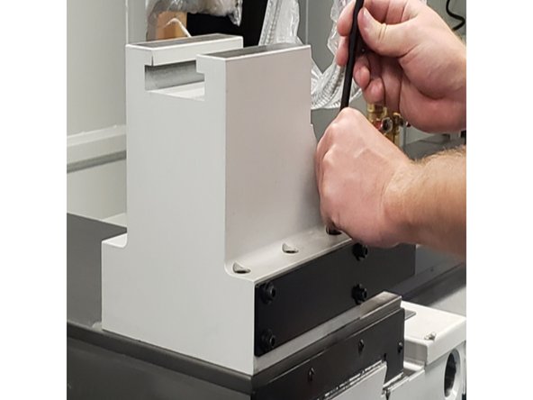
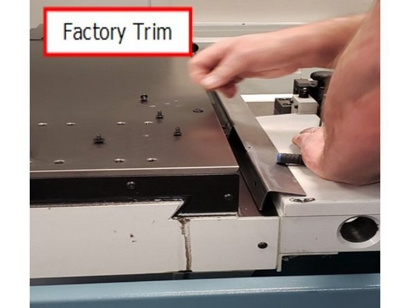
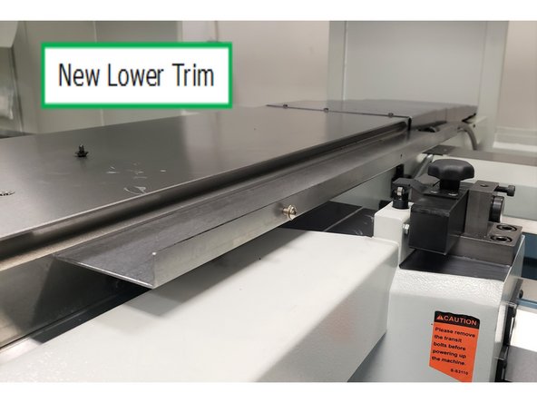
Remove factory trim from right side of table.
-
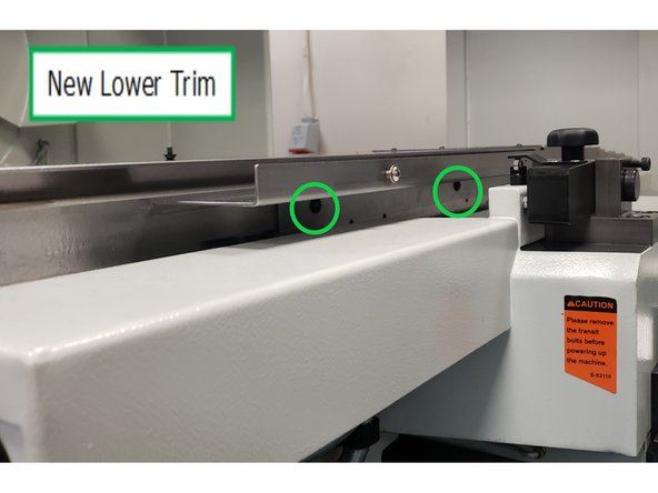
Replace it with the shorter of the two cross slide sheet metal parts provided. Detail shows two screws are installed on the bottom. The outside edge gets three screws to eventually connect with the upper cross slide sheet metal.
-
-
-
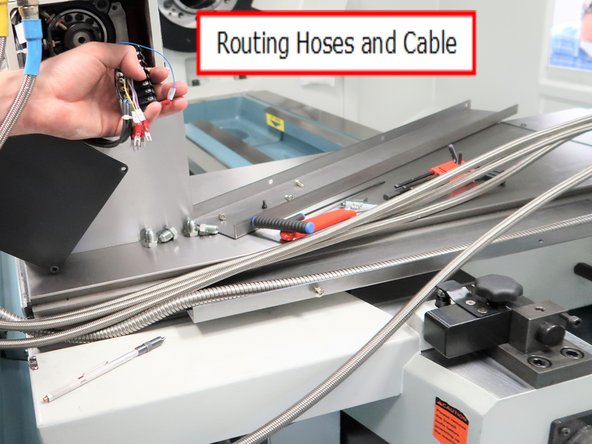
Several hoses and a electric cable need to be routed thru this channel before the upper cover is installed.
-
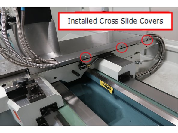
The longer of the two covers is the upper cover. It will be secured by the three screws at the edge of the lower cross slide cover as shown.
-
-
-
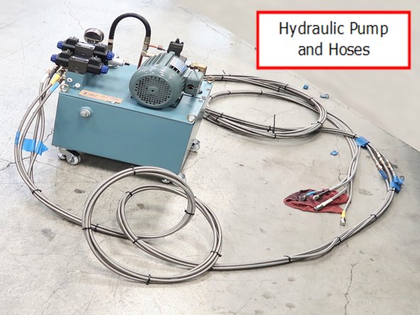
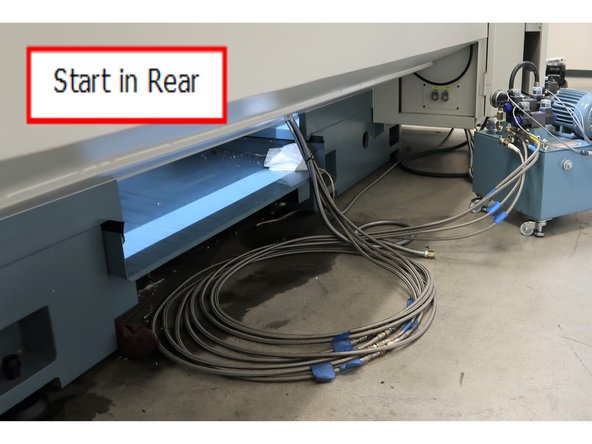
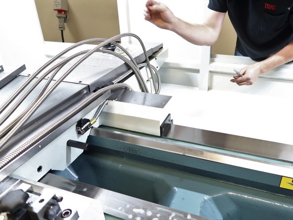
Pump with four hydraulic hose lines are routed through lathe along with a coolant line and turret logic cable. It is suggested that the installer start from the rear of the 30120 to route the hoses. It is difficult to start from the turret end because of lifting the heavy hoses through the lathe.
-
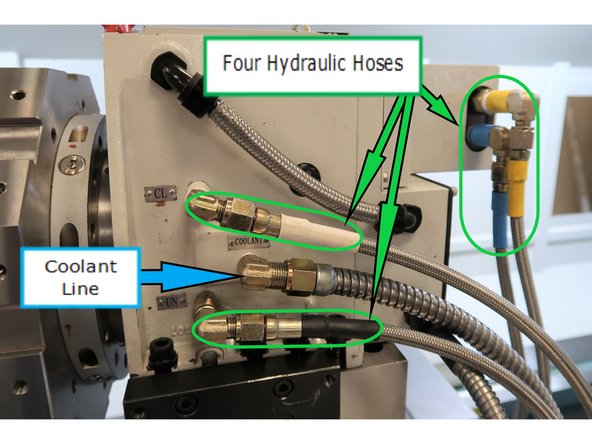
Logic cable from the computer and coolant line from pump located on the chip tray.
-
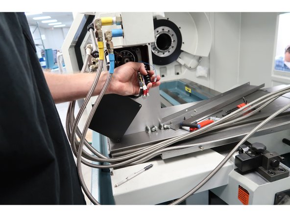
The four hydraulic hoses are exactly the same and difficult to identify them. Layout each of the hoses and mark each one individually. We will use colored heat shrink for color coding to make sure they are marked correctly with both ends the same color. Look at the photos of the pump side and verify which hose goes where.
-
This photo shows you where each color hose goes on the turret.
-
-
-
Tie wrap the hoses, coolant line and turret logic cable together so the far ends are about the same length. Start feeding from the rear near the spindle end of the lathe.
-
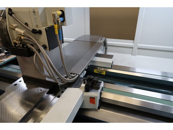
Inside of the lathe position the hose group as shown.
-
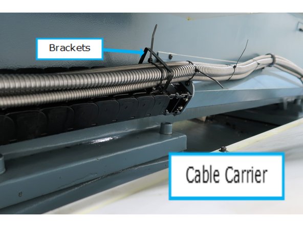
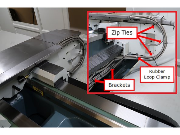
Cable carrier helps organize the hoses and keeps them in position as the table travels back and forth. There are brackets every 18" or so to keep the hoses is position. You will have to feed the hoses through each bracket.
-
Tip: Extend the table toward the far end and route the group through several brackets. Then move the table closer to the spindle and the hoses will make the turn. It is difficult to route 5 hoses and the cable through the brackets by hand while the cable carrier makes its 180 degree turn.
-
-
-
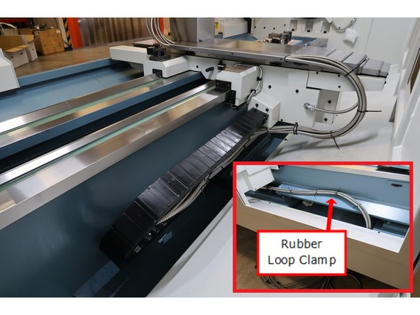
Route the hoses near the table in the lower cross slide. The five hoses and one electric line will fit in the cross slide with the top bolted in place. Use rubber hose clamps to control the hoses from the cable carrier up to the table.
-
-
-
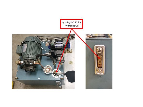
Please note that the TRAK recommended Hydraulic oil is Quality ISO 32 Oil.
-
A full hydraulic system requires 38L of Hydraulic Oil.
-
Check the hydraulic oil level in sight glass on tank on a monthly basis.
-
Drain and refill full hydraulic system on an annual basis.
-
Adjust hydraulic pressure using the PDF guide at the end of procedure.
-
-
-
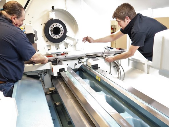
Run the table back and forth along both axis several times and make sure the hoses are secure and there is no binding near the axis limits of travel.
-
Cross slide cover top and bottom in place, hose clamps in place. and cable carrier organized to move back and forth with the table and keep hoses safe and tidy. Organize logic cable and hoses as shown using zip ties and removes ends.
-