-
-
Pump with four hydraulic hose lines are routed through lathe along with a coolant line and turret logic cable. It is suggested that the installer start from the rear of the 30120 to route the hoses. It is difficult to start from the turret end because of lifting the heavy hoses through the lathe.
-
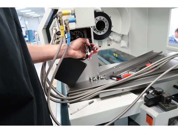
The four hydraulic hoses are exactly the same and difficult to identify them. Layout each of the hoses and mark each one individually. We will use colored heat shrink for color coding to make sure they are marked correctly with both ends the same color. Look at the photos of the pump side and verify which hose goes where.
-
This photo shows you where each color hose goes on the turret.
-
-
-
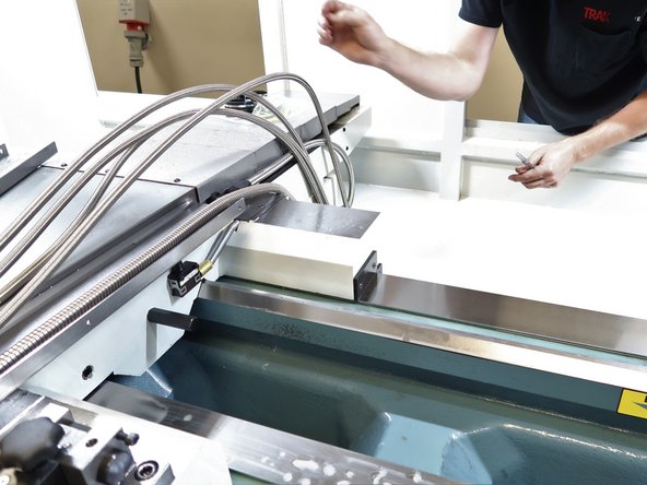
Tie wrap the hoses, coolant line and turret logic cable together so the far ends are about the same length. Start feeding from the rear near the spindle end of the lathe.
-
Inside of the lathe position the hose group as shown.
-
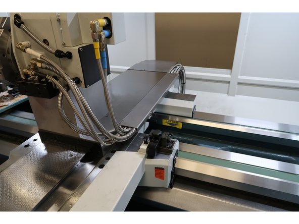
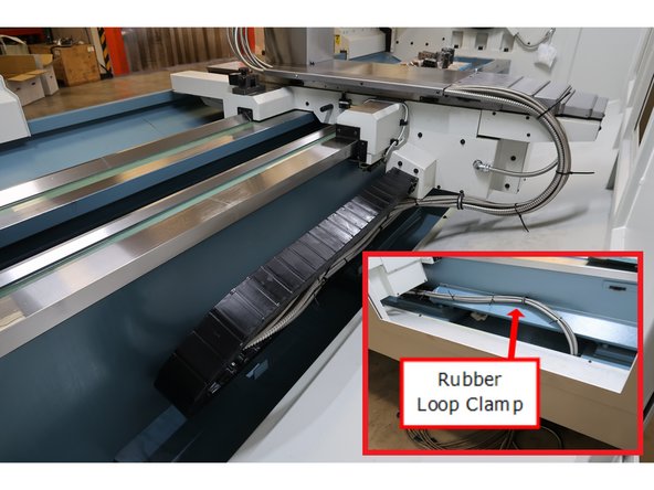
Cable carrier helps organize the hoses and keeps them in position as the table travels back and forth. There are brackets every 18" or so to keep the hoses is position. You will have to feed the hoses through each bracket.
-
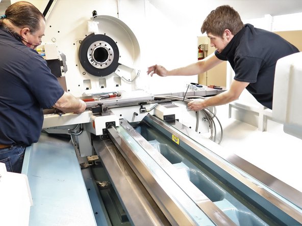
Tip: Extend the table toward the far end and route the group through several brackets. Then move the table closer to the spindle and the hoses will make the turn. It is difficult to route 5 hoses and the cable through the brackets by hand while the cable carrier makes its 180 degree turn.
-
-
-
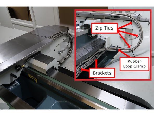
Route the hoses near the table in the lower cross slide. The five hoses and one electric line will fit in the cross slide with the top bolted in place. Use rubber hose clamps to control the hoses from the cable carrier up to the table.
-
-
-
Run the table back and forth along both axis several times and make sure the hoses are secure and there is no binding near the axis limits of travel.
-
Cross slide cover top and bottom in place, hose clamps in place. and cable carrier organized to move back and forth with the table and keep hoses safe and tidy. Organize logic cable and hoses as shown using zip ties and removes ends.
-