Introduction
The following guide describes how to replace a CAT40 arm with a BT40 Option arm on all VMCsi models.
In addition, this guide can also be used to replace a nonfunctioning or damaged arm.
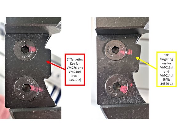
Please note that the targeting keys used on the VMC7/10si Automatic Tool Changer (ATC) arms are different from the ones used on the VMC12/14si; the difference is explained on Step 21 - ATC Arm Targeting Keys of this guide.
Tools
Parts
No parts specified.
-
-
This is a powerful feature of the controller, and without a complete understanding of the ATC and tool change functions, the operator could easily damage the mill or injure the operator.
-
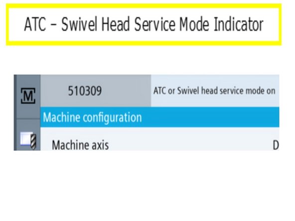
ATC or Swivel Head Service Mode allows manual control of the tool changer for maintenance reasons, as well as to correct situations when the ATC is in an error state, or if there is a problem with the operation.
-
For an explanation of Service Mode please refer to Section 4.0 Automatic Tool Changer, Sub 4.3 ATC or Swivel Head Service Mode of the TRAK VMCsi Siemens Sinumerik CNC - Safety, Installation, Maintenance, Service and Parts List (34104) document for more information on how to manually move and rotate the ATC arm for maintenance purposes.
-
-
-
If the arm is not damaged and can safely be operated, then conduct a tool change to automatically move the spindle to the correct tool change height, see steps below.
-
If there is damage to the arm, the above steps may not be possible. If this is the case, proceed to step 4, which describes how to position the ATC Arm into the home position and uses Parameter 30600 in order to position the spindle to the correct tool change height.
-
Steps to perform a tool change:
-
Press JOG on the Machine Control Panel (MCP).
-
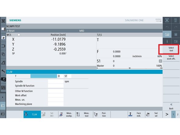
On the touchscreen, (1) press the Machine shortcut key on the left-hand corner of the screen, and then (2) press the Horizontal Soft Key (HSK) "T, S, M."
-
Next, (3) click on the "T" field, and then (4) press the Vertical Soft Key (VSK) "Select tool."
-
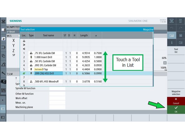
The "Tool selection" window appears. Scroll through the tool list, and choose the tool that you want to load.
-
-
-
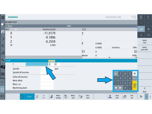
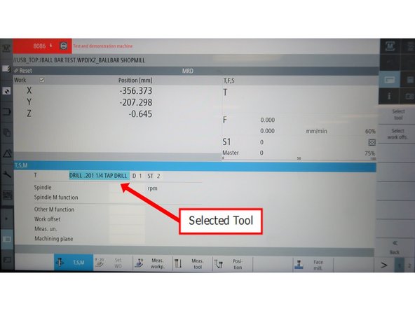
Once you have chosen a tool, its tool details will appear on the "T" field on the screen, as shown on the image.
-
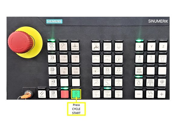
Press CYCLE START on the MCP to change the tool.
-
Once the tool change is complete the ATC arm is in home position and the spindle is at tool change height skip to step 8 to start the ATC Arm removal.
-
-
-
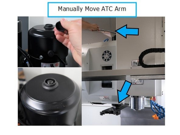
If your ATC has been crashed and your arm is out of position, it can be moved manually by using a 12 mm socket and 3/8 drive ratchet on the top of the motor. If possible, jog Z axis to the top of its travel. If not possible, rotate arm around until you can safely move the Z to top of travel.
-
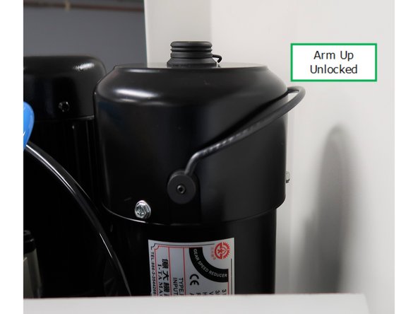
To allow for ease of movement, release motor brake by lifting brake arm up from its original down position. It may fall down, so placing a rag between the arm and the body of the motor can hold it up. Do not use excessive force.
-
Remove bolt cover and rotate the 12mm socket clockwise until the ATC arm reaches its home position.
-
If the ATC Arm has been crashed and is still in the crashed position it may be necessary to move the arm in reverse to clear any tools that may be stuck from the crash. To move the Arm in reverse rotate the socket counter clockwise.
-
The motor is on a 8:1 reduction, so it may take several rotations to see arm movement.
-
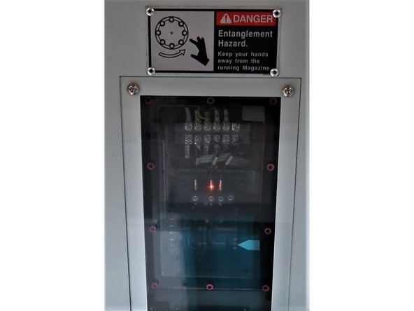
Rotate arm around until center LED is illuminated, which indicates arm is in the home position. When arm is retuned to home, lock it by lowering the lever preventing manual movement. Replace cap.
-
-
-
All ATC safeties are off while in ATC or Swivel Head Service Mode. Use caution while operating mill in this mode, the ATC arm swings at speed. Make sure you are clear of ATC arm path while operating ATC.
-
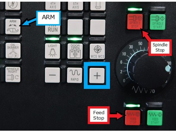
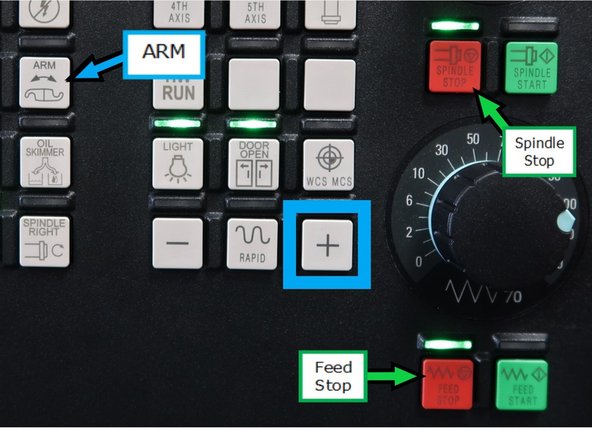
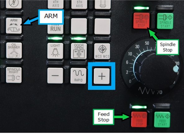
To enter ATC or Swivel Head Service Mode, press and hold red "SPINDLE STOP" button and press red "FEED STOP" three times quickly. Green LED above "FEED STOP" should blink. There should also be a message displayed at the top of the touchscreen when ATC is in Swivel Head Service Mode.
-
Light should blink approximately 1x per second. If this pattern is repeated, the lights will blink faster, indicating other versions of this service mode. Only use the first one, with the slowest blinking. If the wrong mode is entered, press reset button and only follow pattern one time."
-
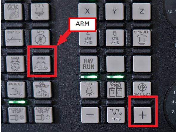
Press and hold the "ARM" button and then press and hold the "+", this will move the ATC arm under the spindle. Verify arm is under spindle in tool change position. Hold the "+" button long enough to ensure ATC arm moves all the way into tool change position. A quick release of the "+" button will not complete the needed arm movement.
-
If arm does not complete movement to the tool change position, press and hold the "ARM" and "-" buttons to return the ATC arm to the home position. Then press and hold the "ARM" and "+" buttons again until the arm reaches the tool change position.
-
-
-
If the arm cannot safely be operated, then reference Parameter 30600 in order to move the spindle to the correct tool change height:
-
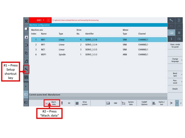
On the touchscreen, (1) press the Setup shortcut key on the left-side bar, and (2) press HSK "Mach. data."
-
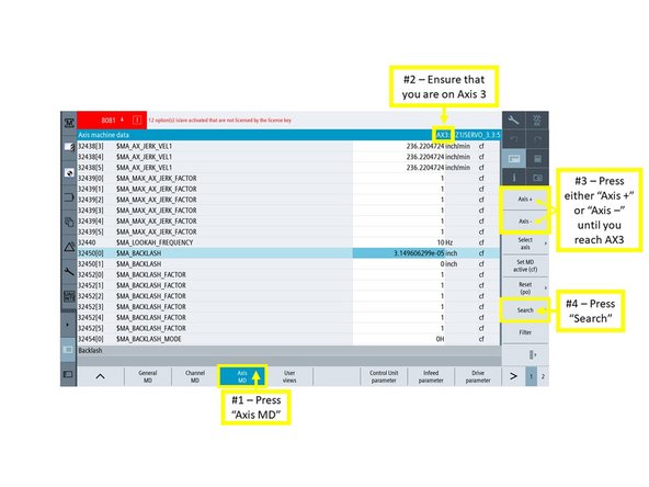
On the next screen, (1) press the HSK "Axis MD." The "Axis machine data" window will appear.
-
As shown on the image, (2) make sure that you are on Axis 3 (Z Axis) in the "Axis machine data" window; (3) press either VSK "Axis +" or "Axis -" until you are in "AX3."
-
Next, (4) press the VSK "Search" on the right side of the screen.
-
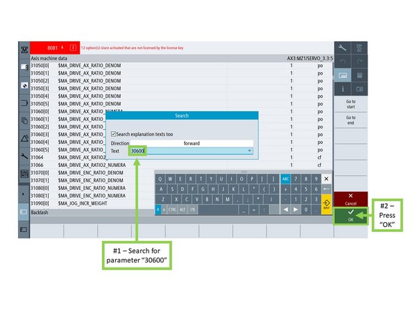
The "Search" window will appear. Under the text field, (1) search for parameter "30600," and (2) press VSK "OK."
-
-
-
The control will automatically search for Parameter 30600[0], which references the specific height for the spindle's tool change position.
-
Note the value listed under Parameter 30600[0] for now.
-
Next, (1) press the Machine shortcut key, and then (2) press VSK "Act. values Machine."
-
Make sure that VSK "Act. values Machine" remains highlighted on the screen during the next step.
-
(3) Jog the spindle to the value that was indicated in Parameter 30600[0]. The spindle should now be at the proper tool change height.
-
Once the spindle is at tool change height move ATC arm back to home by pressing and holding the "ARM" and "-" buttons until arm returns to home position, then exit ATC maintenance mode by pressing the reset button on the MCP.
-
-
-
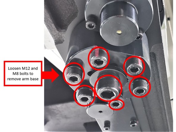
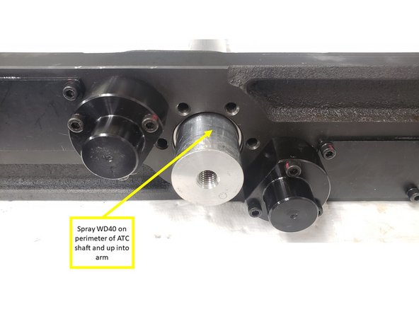
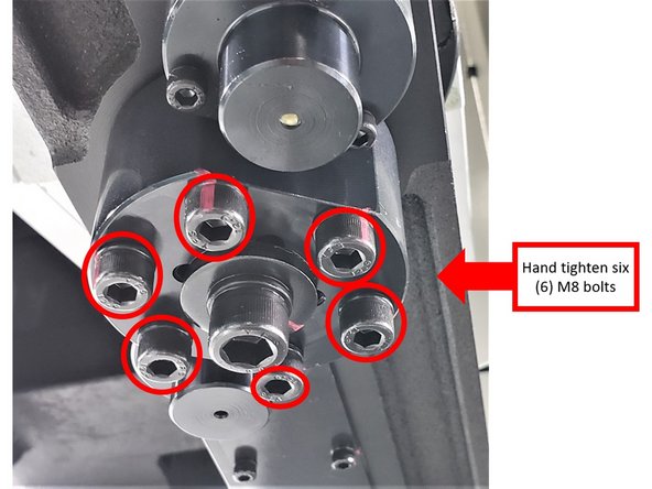
Next, loosen and remove the center M12 and six (6) M8 bolts on the arm base. Remove the base from the ATC shaft. Spray WD-40 on perimeter of ATC shaft and up into arm.
-
Reinstall the base and loosely thread in the M12 bolt (without washer), so it will catch the arm.
-
-
-
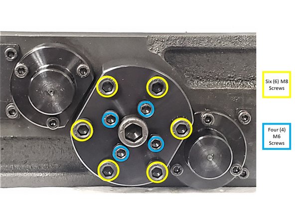
Gradually alternate adjusting the six (6) M8 screws and four (4) M6 30 - 40 mm SHCS on the arm base in order to remove the arm from the ATC shaft (see image for reference):
-
Thread in the M8 screws for two (2) to three (3) turns in the arm base.
-
Install the M6 screws in the arm base until they engage with the bottom of the ATC shaft. The M6 screws are used as jack screws to push the arm off the ATC shaft.
-
Tighten the M8 screws in a cross pattern on the arm base a couple of turns. Make sure arm base does not reengage the taper lock rings. Once the M6 screws are installed, tightening the M8 screws gradually pulls the arm down the shaft, towards the arm base, and the end of the shaft.
-
Once the M8 screws have been tightened a couple of turns, loosen the M8. Doing so lowers the arm base further down the shaft, which also allows the M6 screws to be extended.
-
Tighten the M6 screws again on a cross pattern until they engage with the bottom of the ATC shaft.
-
Repeat the above steps of tightening and subsequently loosening the M8 screws, and then extending the M6 screws (all of the above steps done on a cross pattern) in order to pull the arm down the ATC shaft.
-
-
-
Please note that the arm weighs approximately 25 - 30 lbs. Take proper safety precautions when lowering the arm off the end shaft. You may find it is easier to sit on the table for arm removal. Make sure "E-STOP" is pressed before climbing inside.
-
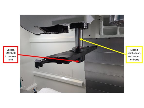
Once the arm becomes loose and rotates freely at the bottom of the shaft (as shown on the image), carefully loosen and remove the M12 bolt, and lower the arm off the end shaft by hand.
-
If the arm is not loose enough to fall off, remove the M12 SHCS and rotate back and forth while pulling down on the arm to remove it.
-
Using the ATC Service Mode, fully extend the shaft; closely inspect it for burrs, and stone any rough edges that may have occurred from the arm removal process. Wipe the shaft with clean rag.
-
Use ATC Service Mode by press "ARM" and holding the "+" key until it moves into tool change position. Then Press green unclamp button on the spindle, hold the "ARM" button and quickly bump "+" button until shaft lowers.
-
-
-
Enable spindle on MCP.
-
Orient the spindle using the control to get to the tool change orientation angle via the following steps:
-
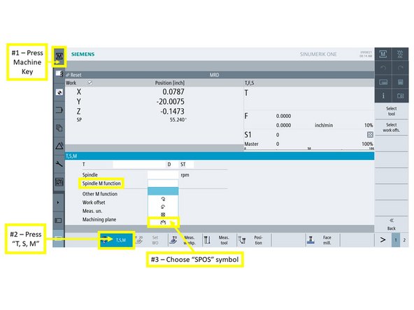
On the touchscreen, (1) press the Machine Mode shortcut key on the top left of the screen, and then (2) press the HSK "T, S, M."
-
The "T, S, M" window appears. (3) Click on the "Spindle M function" field, and choose the last symbol (which is the "SPOS" option) from the dropdown.
-
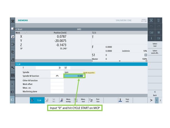
Next, the "Spindle stop position" field will appear. Input "0" on this field, and then press CYCLE START on the MCP.
-
Doing so will automatically orient the Spindle Dogs to the proper tool change orientation angle in relation to the new ATC arm.
-
-
-
Enter ATC or Swivel Head Service Mode.
-
Use arm jog buttons to rotate shaft fully to tool change position.
-
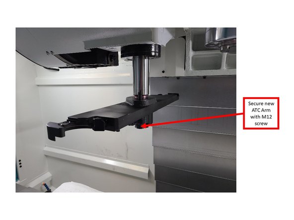
Lift the new ATC arm (which could either be the BT40 Option, or a replacement CAT40 arm) onto the shaft, and loosely screw in the M12 screw and washer to hold the arm in place. The new ATC arm should now rotate freely on the shaft.
-
You may need to omit the washer and work the arm up on the shaft to get the 12mm SHCS started. Install the washer later when torqueing the 12mm SHCS.
-
Due to the new ATC arm rotating freely on the shaft, watch the arm carefully, and make sure that it remains located at a position where it avoids both the spindle and ATC pot area when proceeding with the next steps.
-
-
-
Set up alignment tool on the spindle to make sure that the arm position on the ATC shaft is correct:
-
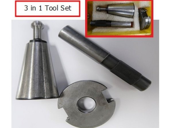
Gather all components of the 3 in 1 Tool Set (tool holder, disc, and alignment bar).
-
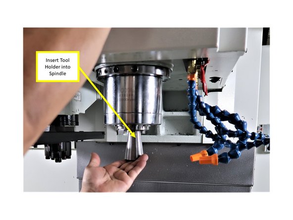
Insert the 3 in 1 tooling (clamping) tool holder into the spindle.
-
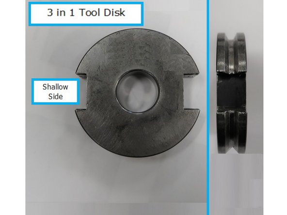
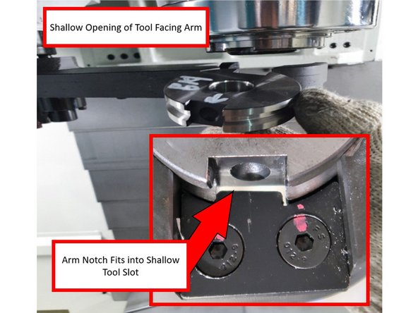
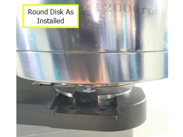
Insert the round disc piece of the 3 in 1 tooling into the ATC arm. Make sure that it is placed in the correct direction; as shown on the image, one side is deeper, and the other side is shallower.
-
-
-
With the shaft raised to the tool change position, the plunger on the ATC arm will be compressed, which will allow the disc to be easily inserted into the arm.
-
Inset photo shows the notch on the arm that needs to align with the shallow side of the disc. Make sure that the notch rests on the shallow slot of the round disc.
-
The image shows a close up of the shallow side of the disc, which is installed on the ATC arm under the spindle.
-
-
-
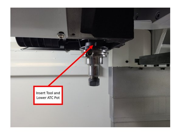
Insert a tool into the ATC pot, and then lower the ATC pot itself. Make sure that the arm is out of the way when lowering the ATC pot. Deep notch in the tool holder should be toward the targeting key in the pot.
-
If the shallow notch is toward the targeting key in the pot. the tool holder will not go all the way up in the pot causing the arm height to be incorrect.
-
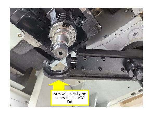
By hand, gently rotate the ATC arm, so that its tool finger is aligned below the tool in the ATC pot; the ATC arm should initially be lower than the tool.
-
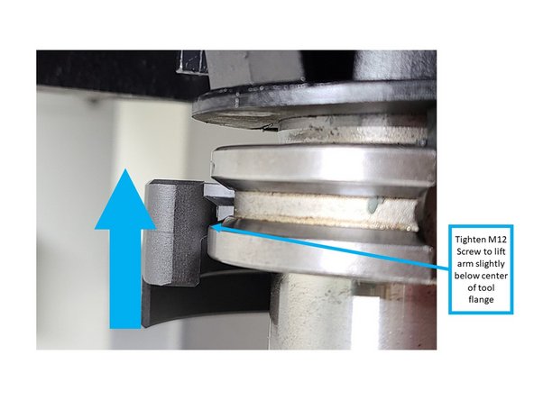
Using the tool for reference, tighten the M12 bolt to lift up the arm, and to begin lining it up with the tool flange.
-
At this point, lift up the arm until the tool finger is only slightly below the center of the tool flange (as shown on the image).
-
-
-
Before raising the arm for final alignment with the center of the tool flange, snug up the M8 screws around the M12 screw to make sure that arm is firmly fixed on the shaft.
-
Please note that the arm should still be able to rotate. Do not overtighten when snugging up the M8 screws; tighten only until they push the arm base to begin making contact with the taper lock rings.
-
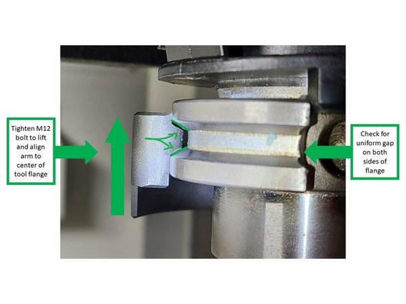
Continue tightening the M12 bolt until the arm reaches the proper height that allows it to have smooth engagement with the tool flange. Check for uniform gap on both sides of the flange.
-
Using a flashlight helps in showing the contrast in alignment between the tool flange and the arm.
-
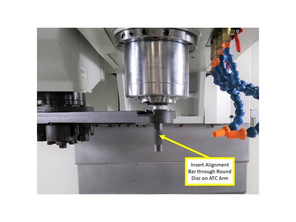
When the arm is raised to the correct height, and is rotated and fully engaged to the tool holder in the ATC pot, double check alignment by inserting the alignment bar of the 3 in 1 tooling through the round disc on the arm and into the spindle (as shown on the image).
-
Tighten the M8 bolts, so that the arm no longer rotates freely on the shaft.
-
Rotate arm to clear tool holder. From the ATC or Swivel Head Service Mode press and hold the "ARM" button then press and hold the "-" button to move the ATC arm back to the home position. Remove tools from spindle and arm, and raise pot.
-
-
-
Assume ARM is in home position, follow instructions below.
-
From the ATC or Swivel Head Service Mode, press and hold the "ARM" button and press and hold the "+", this will move the ATC arm under the spindle.
-
-
-
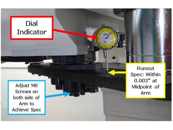
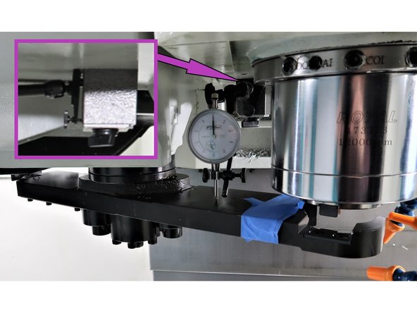
Starting with the ATC arm under the spindle, set up a dial indicator with mag base attached to the ram casting, as shown in the image. Indicator needle should be centered on the arm half way between the shaft and tool finger to measure the level of the ATC arm.
-
The dial indicator on the arm with an inset photo taken from the right side of the mill to show where on ram casting to locate magnetic base.
-
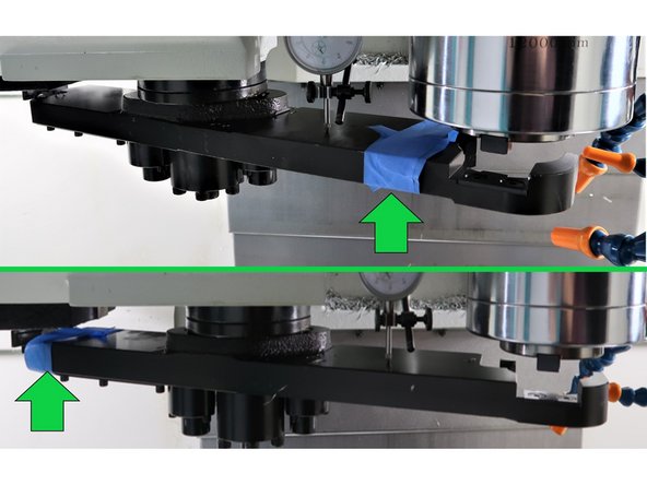
Mark the arm starting position with a piece of tape to keep track of where the arm started and which direction to return the arm to the previous position when leveling. Multiple moves back and forth are needed to get the arm level.
-
To move the Arm to the other side press and hold "SPINDLE UNCLAMP" button for 3 - 5 seconds then press and hold the "ARM" and "+" buttons. To return to previous position press and hold the "ARM" and "-" buttons.
-
Once you press and hold "SPINDLE UNCLAMP" and either "+" or "-" you don't need to press and hold air ("SPINDLE UNCLAMP") button for subsequent moves.
-
If ATC arm is accidentally moved back to the home position, remove the indicator and mag base before moving the arm back under the spindle. If the arm is in the home position the ARM will not move down before it moves under the spindle, if the indicator is still in place it will get damaged!!
-
Use ATC or Swivel Head Service Mode to level both sides of the ATC arm by touching off the indicator at the midpoint of each side of the arm (which is between the shaft and the tool finger; also shown on the image). The specifications for runout (level) should be within .003".
-
If the above spec is not achieved, adjust the respective M8 screws that are located on each side of the ATC Arm. Tightening the M8 screws on one side of the arm will lower that particular side, raising the other side.
-
-
-
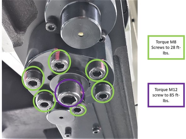
Once leveled, torque M8 screws on a cross pattern to 28 ft-lbs. Then tighten the M12 screw a few turns and recheck. The more steps you make the better the result will be.
-
To maintain level it may be necessary to torque a couple of the M8 screws a little more than 28ft-lbs, but do not exceed 35ft-lbs.
-
Torque the M12 bolt to 85 ft-lbs.
-
Recheck level to verify level has not changed.
-
If not level, readjust M8 screws and verify they are leveled.
-
-
-
Press "Reset" on the MCP to exit ATC or Swivel Head Service Mode.
-
The following steps will place a tool in the spindle and then replace it into the tool magazine.
-
To Pick a Tool From Carousel: Press T, S M from the HSK, then press "Select Tool" from the right VSK.
-
Press any tool located in the carousel (numbered tool list shown in pop up window), to do a tool change press "OK" on the lower right corner of the screen. Press "CYCLE START" on the pendant.
-
Return to Tool Zero: Touch the "T" field as shown in the image and enter "0" for the tool number in the pop up window. Press "INPUT", and "CYCLE START" on the pendant.
-
Perform several tool changes to confirm operation. There should not be any harsh noises. Use caution, as tools may be dropped or ejected if alignment is off.
-
-
-
Each ATC arm has targeting keys on the tool fingers on both sides of the arm.
-
The targeting key lines up with the spindle dogs and the indexing lugs on the ATC pot in order to properly orient the tool holder for a successful tool change.
-
Due to different hardware configurations among the various VMCsi models, the targeting key is different for the ATC arms on the VMC7/10si and the VMC12/14si (please see image):
-
The VMC7/10si have the 5° Targeting Key (P/N: 34519-2).
-
The VMC12/14si have the 10° Targeting Key (P/N: 34520-1).
-
-
-
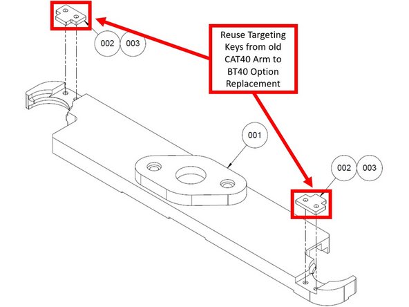
If you are replacing the standard CAT-40 Arm with the BT40 Option (P/N: 34085), the targeting keys should be removed from the old CAT-40 Arm, and then reused on the new BT40 Arm.
-
The old CAT-40 arm should be sent back to the Warehouse to stock as P/N: 34519-1.
-
Cancel: I did not complete this guide.
2 other people completed this guide.


![The control will automatically search for Parameter 30600[0], which references the specific height for the spindle's tool change position.](https://d3t0tbmlie281e.cloudfront.net/igi/trakmtsupport/lCFOipFoUBMGNMoN.medium)
![Note the value listed under Parameter 30600[0] for now.](https://d3t0tbmlie281e.cloudfront.net/igi/trakmtsupport/IaBId3qoH4jCBXZh.medium)
