
Introduction
To operate the spindle probe on a VMCsi machine, the optical receiver must first be installed inside the machine envelope. This receiver communicates with the probe wirelessly. If it hasn't been installed yet, refer to the separate Dozuki guide titled “VMCsi Probe Tool and Probe Part Options – Mount Probe Receiver” for installation instructions.
This guide focuses on setting up and calibrating the OMP40-2 Spindle Probe (P/N: 34080-1). This probe helps streamline the process of setting part zeros, applying work offsets, and checking part geometry. The instructions apply to all VMCsi models, whether you're using a Precision Calibration Tool or not.
If you're working with a Tool Setter Probe instead—specifically the OTS Probe (P/N: 34080-2)—you’ll need the separate Dozuki guide titled “VMCsi Probe Tool Option – Set Up & Calibrate Tool Setting Probe.”
At the end of this guide, you’ll also find supporting documentation for Part Number 34050 and the OMP40-2 instruction manual, which detail material locations and assembly information related to the Probe Part Option.
Tools
Parts
No parts specified.
-
-
Thread the stylus (P/N: 34080-5) into the OMP40-2 probe (P/N: 34080-1) using the Renishaw-supplied tool.
-
Torque the stylus to 1.3 – 1.6 lbf-ft.
-
Only use the provided tool—it’s designed to flex before applying too much torque, preventing damage to the probe.
-
Insert the probe into the CAT40 shank (P/N: 34080-8).
-
Use a 2mm Allen wrench to tighten the six set screws on the shank.
-
The shank includes two upper pointed screws and four lower flat screws.
-
Torque all screws to 0.4 – 1.1 lbf-ft.
-
Install the retention knob (P/N: 26800-2) into the CAT40 shank.
-
-
-
Use a flat head screwdriver to remove the battery cover from the OMP40-2 probe.
-
Take out the batteries, wait 5 seconds, then reinstall them and secure the cover.
-
Do not allow coolant or debris to enter the battery compartment.
-
Watch for the LED to flash red, then green, then blue.
-
When the blue LED appears, deflect and hold the stylus to enter configuration mode.
-
Do not remove the batteries while the probe is in configuration mode.
-
To exit configuration mode, leave the stylus untouched for 20 seconds.
-
Battery status will flash: 8 red = good, red + blue = low.
-
-
-
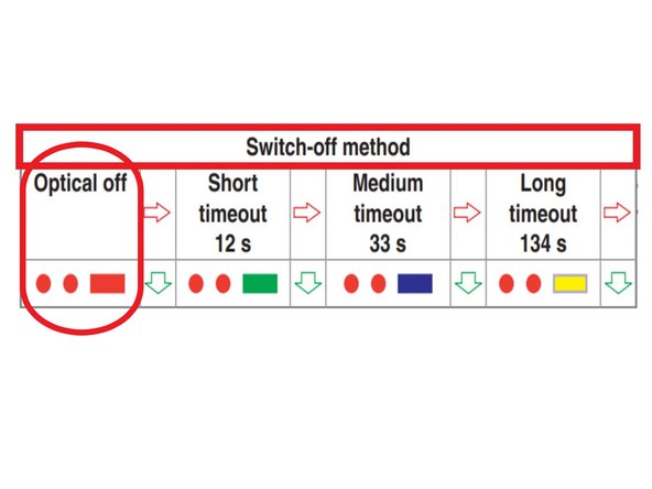
While still holding the stylus deflected, the switch-off method will be displayed via LED flashes.
-
Release the stylus when you see two red flashes followed by a long red flash.
-
To cycle through switch-off options, deflect and release the stylus quickly (1 second).
-
When the correct setting is shown, deflect and hold the stylus for 4+ seconds to continue.
-
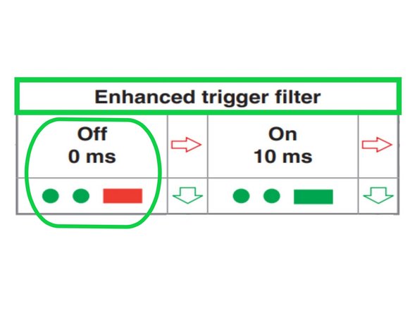
The trigger filter menu will display as two green flashes followed by a long red flash.
-
Deflect and release the stylus to cycle through available trigger filter options.
-
When the correct setting appears, deflect and hold the stylus for 4+ seconds.
-
The probe will automatically move to the next configuration menu.
-
-
-
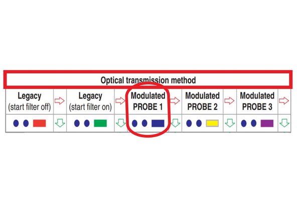
The optical transmission method menu will display.
-
If the probe flashes a color other than blue, deflect and release the stylus (1 second) to cycle through settings.
-
Once the probe flashes only blue, deflect and hold the stylus for 4+ seconds to confirm.
-
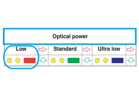
The optical power setting menu will now appear.
-
Deflect and release the stylus until you see two yellow flashes followed by a long red flash.
-
Leave the stylus untouched for 20+ seconds to save and exit configuration mode.
-
-
-
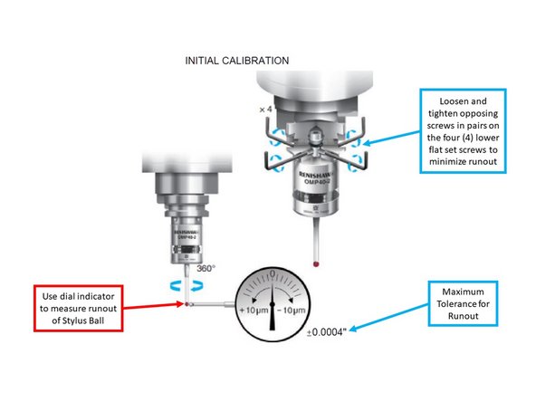
Load the OMP40-2 probe into the spindle.
-
Use a dial indicator to check runout at the ruby tip while turning the spindle by hand.
-
For initial calibration, keep runout within ±0.0004".
-
Adjust the four lower flat set screws in opposing pairs to reduce runout.
-
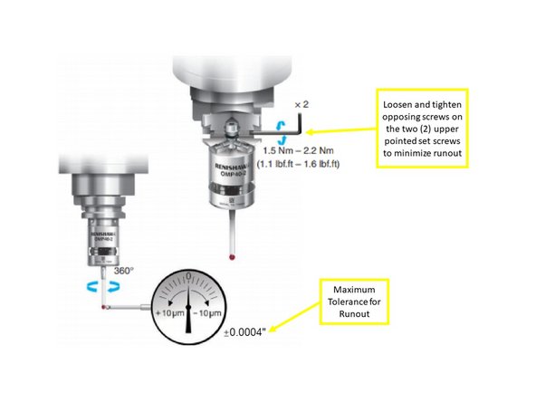
Fine-tune using the two upper pointed set screws, also in opposition.
-
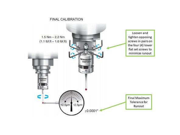
For final calibration, reduce runout to ±0.0001" or better.
-
Re-adjust the lower screws as needed.
-
Finish by adjusting the upper screws until final tolerance is achieved.
-
-
-
On the Machine Control Panel (MCP), press [JOG].
-
On the touchscreen, press [M] (top-left shortcut key) to open the Machine menu.
-
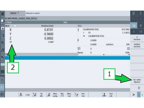
Press [Act. values Machine] to switch to machine coordinates.
-
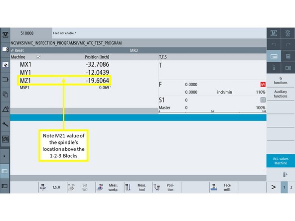
Confirm that axis values now begin with an M (e.g., MZ1), showing machine positions.
-
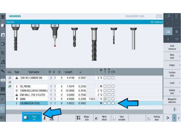
Press [Tool List] (second shortcut key on the left-side bar).
-
Choose a tool location outside of the ATC range (not positions #1–24).
-
Press [New tool] on the right-side softkeys to begin creating the probe tool.
-
-
-
In the [New tool - favorites] window, select [710 - 3D probe] from the list.
-
Press [OK] to confirm the tool type.
-
In the [Tool list] window, enter the probe's length:
-
Use an 8" caliper to measure from the stylus tip to the top of the flange, then add 0.25".
-
Enter this number in the [Length] field.
-
Measure the diameter of the stylus ruby using a caliper (or check the packaging).
-
Enter this value in the [ø] (diameter) field.
-
-
-
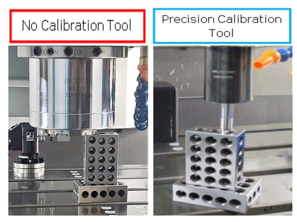
Determine which calibration tool your shop is using.
-
No Calibration Tool:
-
Use Steps 9
-
Precision Calibration Tool:
-
Use Steps 10 -12
-
-
-
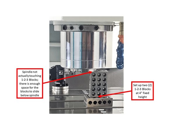
Stack two 1-2-3 blocks vertically to create a 4" fixed height on the machine table.
-
Jog the spindle down until it just blocks the stacked blocks from sliding underneath.
-
Carefully jog the spindle up until the blocks slide freely beneath the spindle.
-
The spindle should be slightly above the blocks—not touching them.
-
Record the MZ1 value shown on the screen at this height.
-
This value will be used later in Step 15 to calibrate probe length.
-
-
-
Press [T, S, M] on the touchscreen.
-
Press [Work offset] to open the offset menu.
-
Select an available offset (e.g., G54) from the list.
-
Press [CYCLE START] on the MCP to activate the selected offset.
-
Confirm the offset name (e.g., G54) appears on the screen.
-
Press [Select tool] to begin loading the calibration tool.
-
If the calibration tool is already listed in the Tool List, skip to Step 13.
-
If not, continue to Step 11 to manually add the calibration tool.
-
-
-
In the [New tool – favorites] window, press [Spec. tool 700–900].
-
Select [725 – Calibrating tool] as the tool type.
-
Press [OK] to add it to the Tool List.
-
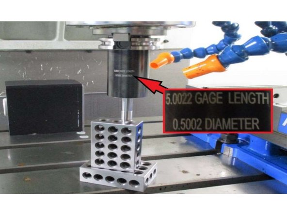
Once added, enter the tool length and diameter using the on-screen keypad.
-
Refer to the engraved values on the calibration tool body for accurate measurements.
-
To insert the tool, press [JOG] on the MCP.
-
Press [T, S, M], then press [Select tool].
-
Load the calibration tool into the spindle, and press [CYCLE START].
-
-
-
Lower the calibration tool below the height of the stacked 1-2-3 blocks.
-
Slowly raise the tool until the blocks just slide underneath it without contact.
-
Press [Act. values Machine] to toggle off machine values—this switches the display to work offset values.
-
Press [Z=0] on the vertical softkey panel.
-
Confirm the Z-axis display now shows 0, setting your reference point.
-
-
-
Press [T, S, M] on the touchscreen.
-
Click on the T field, then press [Select tool].
-
In the Tool Selection window, choose the 3D Probe Tool you previously created.
-
Press [OK] to confirm the tool selection.
-
Press [CYCLE START] on the MCP.
-
Press [DOOR OPEN] to unlock the machine door.
-
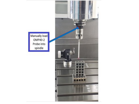
Insert the OMP40-2 probe into the spindle.
-
After loading, verify the T field now displays the 3D Probe Tool.
-
-
-
Press [Meas. workp.] on the touchscreen.
-
Press [Calibrate probe] to open the calibration window.
-
In the calibration window, press [Length] to begin length calibration.
-
If you're not using a calibration tool, enter the MZ1 value recorded in Step 9 into the Z0 field.
-
If you are using a calibration tool, enter 0 in the Z0 field.
-
Jog the Z-axis down until the OMP40-2 probe is about 0.5" above the 1-2-3 blocks.
-
Confirm that the setup is correct before proceeding to calibration in the next step.
-
-
-
With the probe positioned above the 1-2-3 blocks, press [CYCLE START] on the MCP.
-
The probe will automatically move down and touch the top of the blocks to measure its length.
-
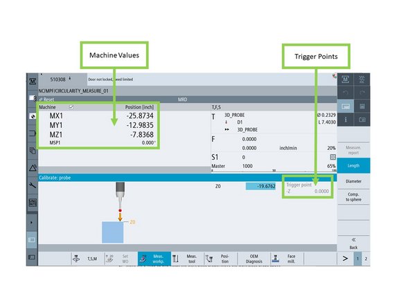
Once complete, the Calibrate: probe window will display the machine values and trigger points.
-
Repeat the probe length calibration three times to ensure consistent results.
-
After each run, check that the machine values and trigger points remain stable and repeatable.
-
-
-
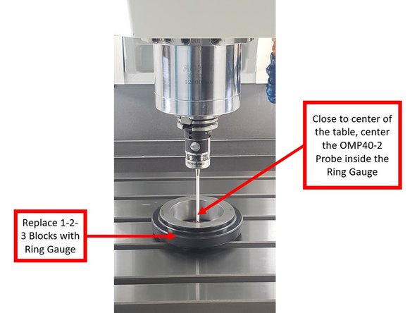
Remove the 1-2-3 blocks from the worktable.
-
Place the ring gauge near the center of the table.
-
Secure the ring gauge using magnets, clamps, or other stable supports to prevent movement.
-
Jog the spindle so the probe's stylus ball sits inside the center of the ring gauge, below the rim.
-
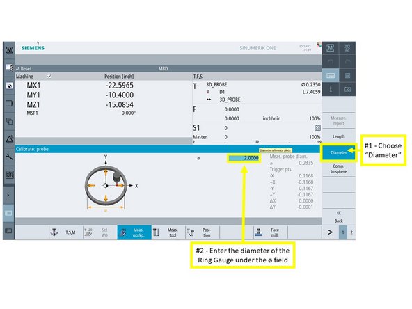
On the Calibrate: probe window, press [Diameter].
-
Enter the known diameter of the ring gauge into the ø field.
-
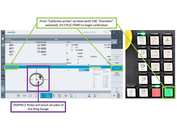
Press [CYCLE START] on the MCP to begin the calibration cycle.
-
The probe will automatically touch all inner sides of the ring gauge to determine diameter.
-
-
-
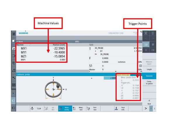
After the cycle completes, the Calibrate: probe window will display the machine values and trigger points.
-
Run the diameter calibration three times to verify consistency.
-
After each cycle, confirm the machine values and trigger points are repeatable.
-
If the results vary between runs, lower the program feedrate and repeat the process.
-


![On the Machine Control Panel (MCP), press [JOG].](https://d3t0tbmlie281e.cloudfront.net/igi/trakmtsupport/j2nVQDPEBqKwQv4p.medium)
![On the touchscreen, press [M] (top-left shortcut key) to open the Machine menu.](https://d3t0tbmlie281e.cloudfront.net/igi/trakmtsupport/oLprl46fijqFQcmL.medium)
![Press [Act. values Machine] to switch to machine coordinates.](https://d3t0tbmlie281e.cloudfront.net/igi/trakmtsupport/LRPYDCrTjtnLFOln.medium)
![In the [New tool - favorites] window, select [710 - 3D probe] from the list.](https://d3t0tbmlie281e.cloudfront.net/igi/trakmtsupport/tgYRgsWwmaAyQoxO.medium)
![Press [OK] to confirm the tool type.](https://d3t0tbmlie281e.cloudfront.net/igi/trakmtsupport/nCRcIBCqyeiByFwn.medium)
![In the [Tool list] window, enter the probe's length:](https://d3t0tbmlie281e.cloudfront.net/igi/trakmtsupport/NO3Pb6jqryXbUXuo.medium)
![Press [T, S, M] on the touchscreen.](https://d3t0tbmlie281e.cloudfront.net/igi/trakmtsupport/PSXbKxMXVmNfXN3X.medium)
![Press [Work offset] to open the offset menu.](https://d3t0tbmlie281e.cloudfront.net/igi/trakmtsupport/OTCWrxhAELAZdthH.medium)
![In the [New tool – favorites] window, press [Spec. tool 700–900].](https://d3t0tbmlie281e.cloudfront.net/igi/trakmtsupport/wDf4RcKRQ1ZEFJ3h.medium)
![Select [725 – Calibrating tool] as the tool type.](https://d3t0tbmlie281e.cloudfront.net/igi/trakmtsupport/3p4GMDdNVDaaORq1.medium)
![Press [OK] to add it to the Tool List.](https://d3t0tbmlie281e.cloudfront.net/igi/trakmtsupport/xtCRgmwBbnIAIoCi.medium)
![Press [Act. values Machine] to toggle off machine values—this switches the display to work offset values.](https://d3t0tbmlie281e.cloudfront.net/igi/trakmtsupport/wRwVGOHpIEcZUMmn.medium)
![Press [T, S, M] on the touchscreen.](https://d3t0tbmlie281e.cloudfront.net/igi/trakmtsupport/SQpFeYSRHKFarIx1.medium)
![Click on the T field, then press [Select tool].](https://d3t0tbmlie281e.cloudfront.net/igi/trakmtsupport/4dZ13LkPSLqLWopi.medium)
![Press [Meas. workp.] on the touchscreen.](https://d3t0tbmlie281e.cloudfront.net/igi/trakmtsupport/Ixb26QHEifLVinIP.medium)
![Press [Calibrate probe] to open the calibration window.](https://d3t0tbmlie281e.cloudfront.net/igi/trakmtsupport/UjfY3wuw6461BSX2.medium)
![In the calibration window, press [Length] to begin length calibration.](https://d3t0tbmlie281e.cloudfront.net/igi/trakmtsupport/YGQbEhinQTQ21daF.medium)
![With the probe positioned above the 1-2-3 blocks, press [CYCLE START] on the MCP.](https://d3t0tbmlie281e.cloudfront.net/igi/trakmtsupport/xOfrUqZtB4IHMNgB.medium)
Cancel: I did not complete this guide.
One other person completed this guide.