Introduction
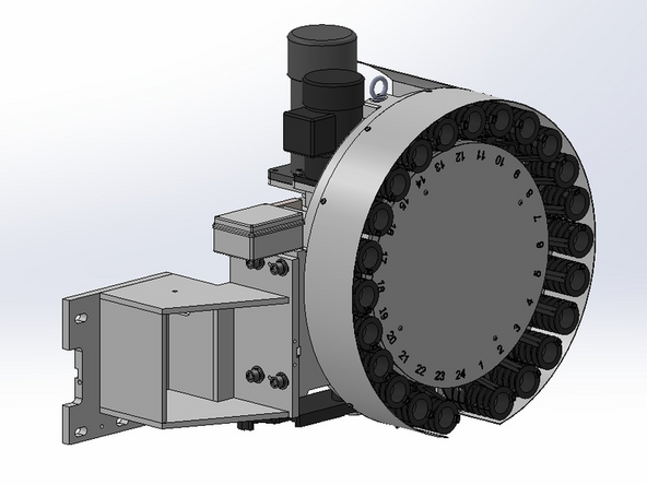
Trak Machine Tools offers 2 different ATC sizes on the VMCsi 12 and 14 series machines. There is the standard 30 tool unit and an optional 40 tool ATC.
This guide will teach the user how to remove the standard 30 Tool ATC and replace it with the optional 40 Tool.
Parts
No parts specified.
-
-
If the machine came pre-equipped with a 30 Tool ATC, the first step in installing a 40 Tool ATC is the removal of the 30 tool. If the machine didn't have an ATC installed skip to step 9 to start the installation of the 40 Tool ATC.
-
Before removing any electrical wiring turn power off at the main machine breaker and lock out.
-
Start by disconnecting the wiring and cable conduit from the junction box on the ATC.
-
There is a cable junction box attached to the back of the ATC assembly, above the ATC adapter bracket. Using a Phillips Head Screwdriver loosen the four (4) screws from the top of the cable junction box and remove the lid.
-
Remove the wires from the terminal blocks for the three (3) cables that go to the machine's electrical cabinet.
-
Remove the conduit fitting holding the conduit with the three (3) cables to the junction box.
-
Remove the three (3) cables and conduit that go to the machine's electrical cabinet from the junction box keeping the fitting with them. You will need to remove these (3) cables from the electrical cabinet and replace them with the ones supplied in the kit as these are too short for the 40 Tool ATC.
-
-
-
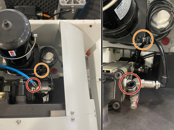
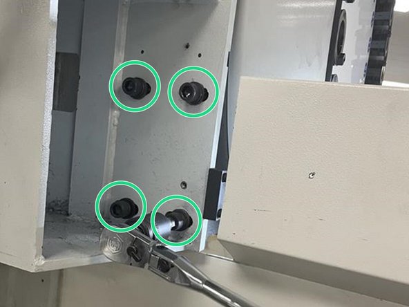
Looking in from the top of the ATC assembly, locate the blue and black air lines and remove them from the fittings on the ATC assembly.
-
Remove the black line from the T-Fitting and leave the jumper on the ATC assembly.
-
Move the airlines to a safe position they will be needed later when installing the new ATC.
-
Note: These lines may need to be replaced with longer lines for the 40 tool ATC
-
-
-
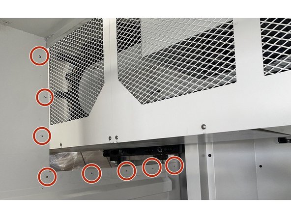
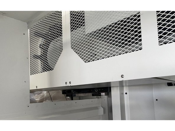
Using a Philips Head Screwdriver remove the eight (8) screws holding the sheet metal cover behind the ATC assembly.
-
Remove the sheet metal cover opening up more space behind the ATC assembly.
-
-
-
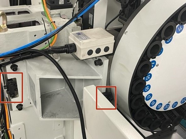
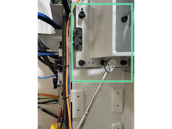
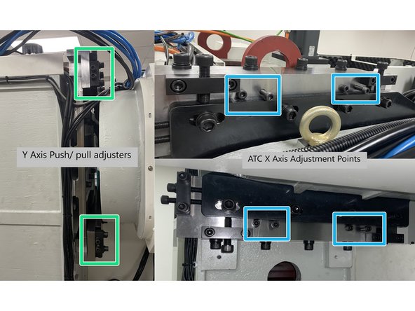
There are two (2) adjustment blocks used for the fine positioning of the ATC. Two (2) screws are used to hold the block and two (2) screws are used to push/pull the ATC into the correct position.
-
There is an adjustment block located behind the ATC bracket, the other adjustment block is located next to the ATC assembly.
-
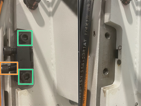
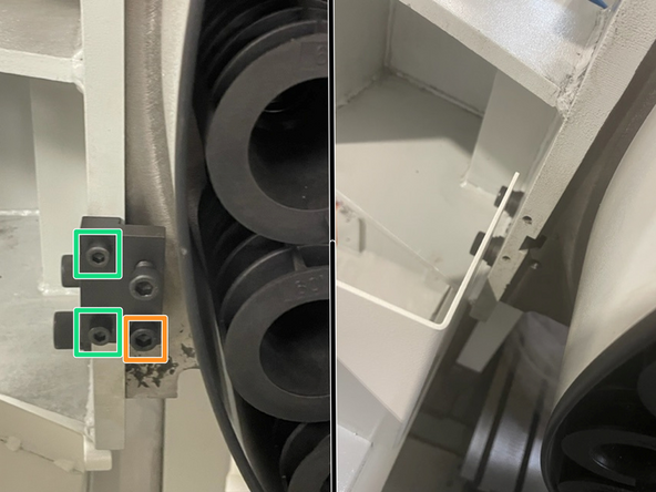
For each block:
-
First remove the screw used for pulling the ATC into position.
-
Then remove the two (2) screws used for holding the adjustment block to the castings.
-
Keep adjustment blocks and hardware for use when installing the new ATC.
-
-
-
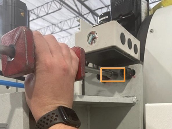
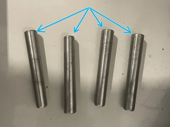
There are four (4) pins used to hold the position of the ATC bracket and assembly that need to be removed.
-
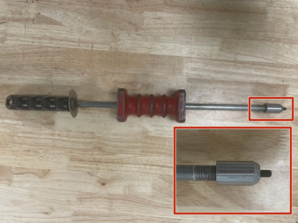
Set up the Slide Hammer with an M6 Bolt that will be used for removing the pins holding the ATC bracket and assembly.
-
Thread the M6 Bolt on the Slide Hammer into the pins on the ATC bracket and the ATC assembly, then slide the handle, with force, away from the pins to remove them.
-
Keep the four (4) pins for use when installing the new ATC.
-
-
-
24T ATC assembly weight: ...lbs (...kg).
-
30T ATC assembly weight: 800lbs (360kg).
-
40T ATC assembly weight: 1650lbs (750kg).
-
24T ATC bracket for VMC7/10si weight: ...lbs (...kg).
-
30T ATC bracket for VMC7/10si weight: 132lbs (60kg).
-
30T ATC bracket for VMC12/14si weight: 158lbs (72kg).
-
40T ATC bracket for VMC12/14si weight: 330lbs (150kg).
-
-
-
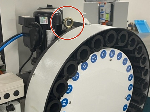
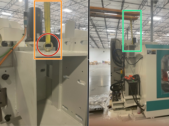
There is an eyebolt threaded into the top of the ATC assembly. Ensure the eyebolt is fully threaded into the ATC assembly.
-
Attach a lifting strap with sufficient rating to the eyebolt and lifting apparatus.
-
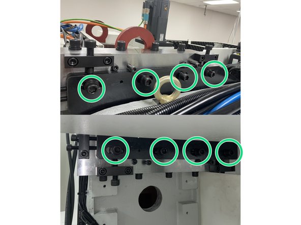
Take the slack out of the strap using the lifting apparatus and with an M14 Hex bit remove the (6) M16 socket head cap screws holding the ATC assembly to the ATC bracket.
-
The 24T ATC assembly is held in place with four (4) sets of mounting hardware. The 30T and 40T ATC assembly is held in place with six (6) sets of mounting hardware.
-
Keep the hardware for use when installing the new ATC.
-
Carefully lift the ATC assembly out through the top of the machine and mount to the storage/shipping bracket.
-
The ATC assembly is keyed to the ATC bracket, take care when removing the ATC assembly so it slides off the keys without causing damage.
-
-
-
There is an eyebolt threaded into the top of the ATC bracket. Ensure the eyebolt is fully threaded into the ATC bracket.
-
Attach a lifting strap with sufficient rating to the eyebolt and lifting apparatus.
-
Take the slack out of the strap using the lifting apparatus and with an M14 Hex bit remove the six (6) sets of mounting hardware holding the ATC bracket to the machine column.
-
Keep the six (6) sets of mounting hardware for use when installing the new ATC.
-
Carefully lift the ATC bracket out through the top of the machine and place on a pallet.
-
The ATC bracket is keyed to the machine column, take care when removing the ATC bracket so it slides off the keys without causing damage.
-
-
-
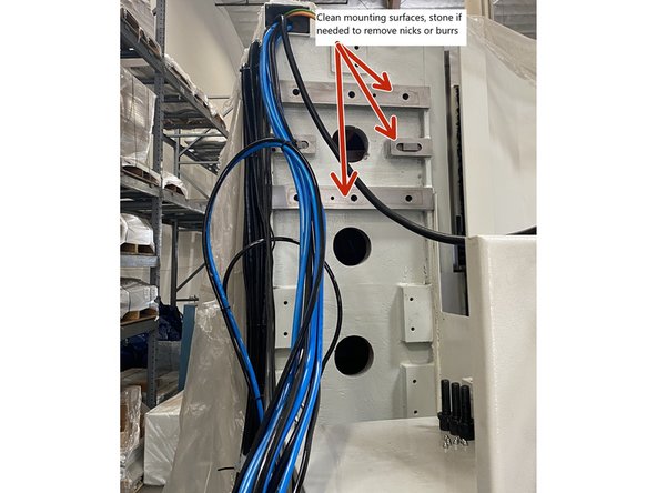
Clean mating surfaces on the machine column and on the ATC mounting bracket.
-
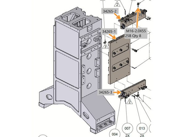
Attach Bracket Top X-Adjustment (34265-2) and Bracket Bottom X-Adjustment (34265-3) to Bracket Mounting 40T ATC (34265-1) with (4) M16-2.0 X 55 SHCS per bracket and tighten. See Photo 2
-
Install 2 of the 4 Bracket Adjustment-40T ATC Level (34246) to the Top X Adjustment Bracket (34265-2) with 4 M12-1.75X30 SHCS and tighten. Install two (2) M12 eye bolts into the threaded holes in the Level adjustment brackets for lifting the ATC bracket up onto to the machine column.
-
Attach a lifting strap with sufficient rating to the eyebolts and lifting apparatus and raise the mounting bracket over the machine. Carefully lower the ATC bracket in through the top of the machine.
-
With the keys lined up between the machine column and ATC bracket use the M14 Hex bit to install the original six (6) sets of mounting hardware.
-
Tighten the 6 (six) sets of mounting hardware to 150ft-lbs of torque.
-
Before installing the 40 Tool ATC remove the 2 leveling brackets we attached the eye bolts to. This makes installing the ATC easier, we will reinstall them in a later step.
-
-
-
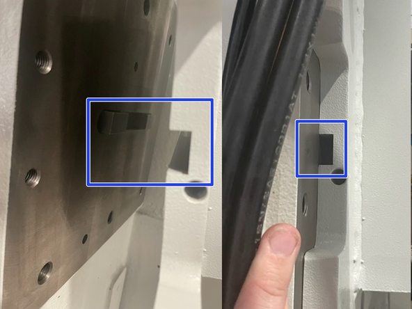
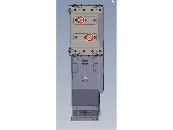
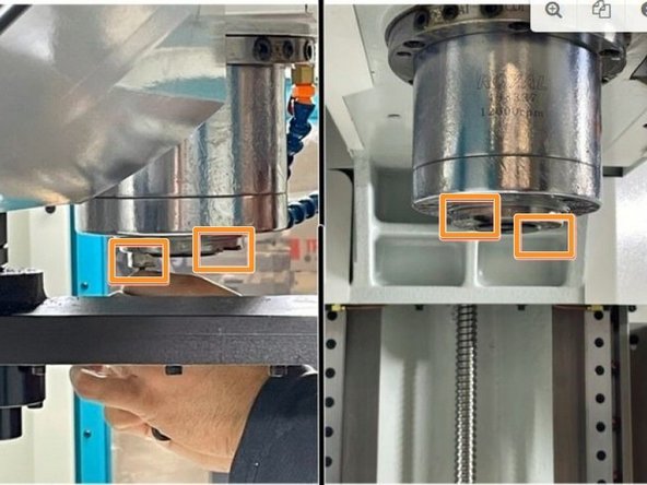
Before installing the 40 Tool ATC onto the mounting plate we need to pin the mounting plate to the column.
-
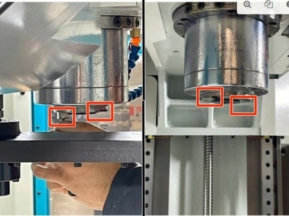
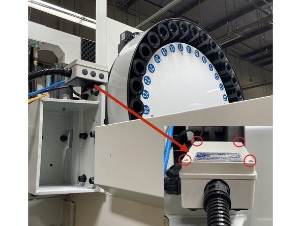
Using a 9mm drill bit add 2 holes 4.25" deep where the pins will be placed for holding the ATC bracket and Assembly in position. (Locations circled in red in Photo 1)
-
Using the #7 tapered reamer open up the holes 4" deep so they follow the taper of the pins.
-
The 40 tool ATC assembly has (2) eye bolts in it for lifting. Ensure both are fully threaded into the assembly. Clean mating surfaces between ATC bracket and ATC assembly. Stone if needed to remove any burrs or nicks.
-
Attach a lifting strap of sufficient rating and hoist the ATC assembly from the storage/shipping bracket into position next to the ATC bracket.
-
The ATC assembly is front heavy. When lifting with a strap it will lean slightly towards the arm side of the ATC assembly.
-
Carefully lower the ATC assembly in through the top of the machine.
-
With the ATC assembly positioned next to the ATC bracket you will need to get one screw started and then use that as a pivot point to raise or lower the ATC assembly to line up the other screws and get them started. Install all (8) mounting screws and tighten them but don't torque them yet.
-
-
-
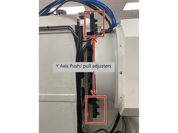
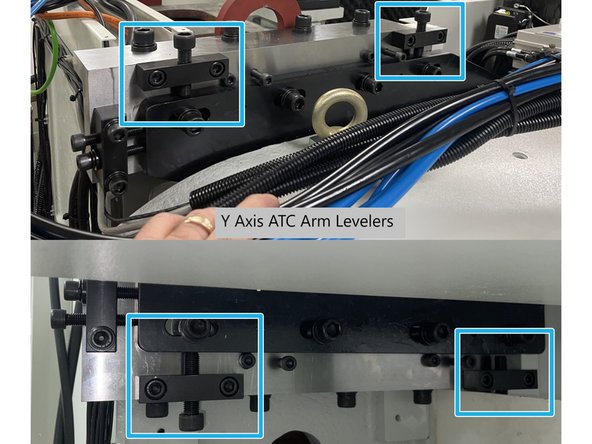
Now that the ATC is installed to the adapter plate you need to install the (2) push/pull brackets (P/N 34245) for the Y axis position adjustment. There is one near the bottom rear of the adapter plate and one near the top rear. Install the mounting screws and tighten them leaving the push/pull screws loose for now.
-
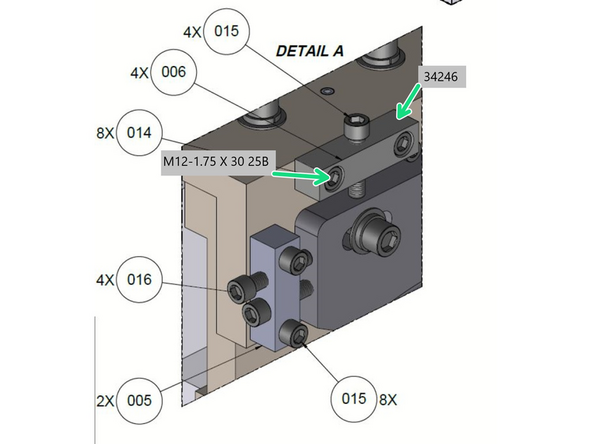
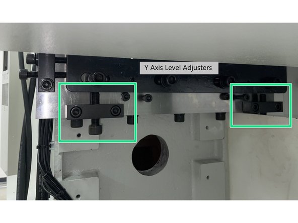
There are also (4) push brackets (P/N 34246) used to level the ATC in the Y Axis. These mount to the adapter plate with (2 ) on the bottom and (2) on the top of the adapter plate, one at each of the 4 corners.
-
Install the mounting screws and tighten them. Tighten the lower push screws until they make contact with the ATC mounting bracket, leave the upper push screws loose for now
-
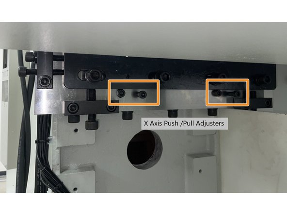
Finally there (4) push pull screw locations to adjust the X Axis position of the ATC. Install (2) M10 X 55 SHCS to the Adapter plate in each of the (4) locations. There are (2) locations on the bottom of the adapter and (2) on the top. See Photo 3. (Top locations not shown in photo)
-
-
-
Note: If this is a 30 to 40 Tool ATC upgrade you will need to remove the existing cables from the electrical cabinet to the ATC junction box and replace with the cables in the installation kit. The existing cables are too short.
-
For machines configured for a 40 Tool ATC from Taiwan the electrical cabinet wiring should already be done, in this case skip to Step 14 to wire the cables to the junction box on the ATC.
-
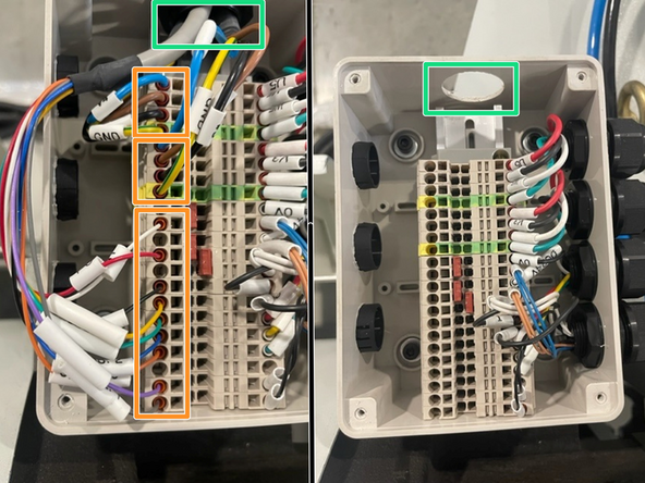
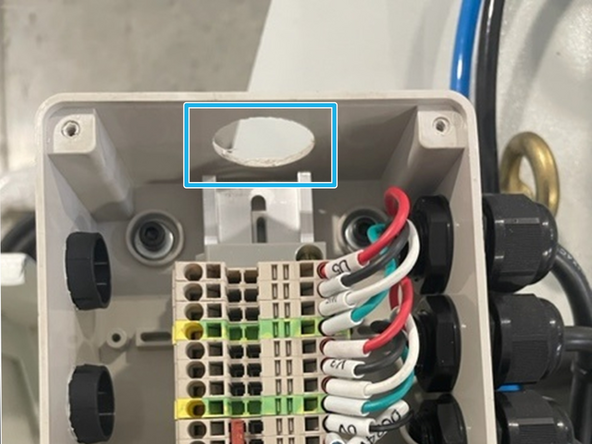
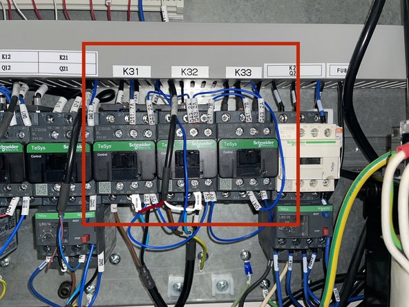
Locate K31, 32 and 33 and install them in the electrical cabinet on the DIN rail next to the K21 relay. Once the relays have been installed attach the labels that identify them to the wire way above them. See Photo 1
-
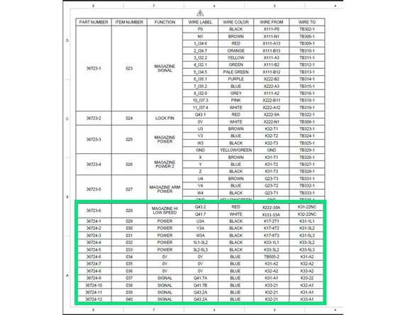
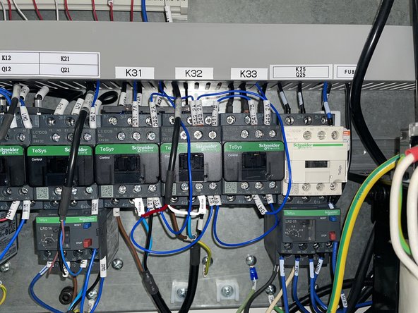
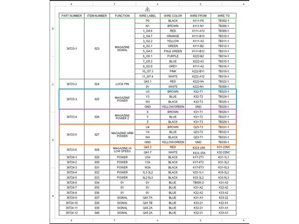
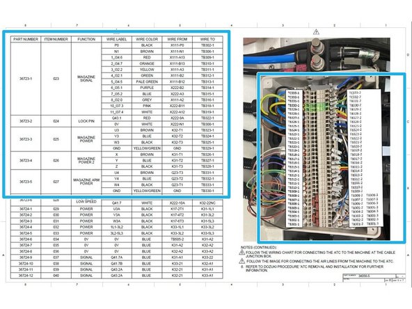
Locate the 36723-6 cable and the (12) 36724-1 through -12 wires and wire the K31 through K33 relays. Use the wiring chart and photo in Photos 2 and 3 for reference.
-
-
-
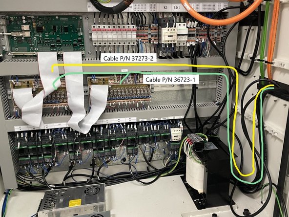
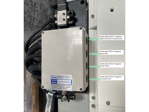
Install cables 36723-1 (Magazine Signal) and 36723-2 (Lock Pin) into the electrical cabinet and wire them up to I/O X111 and X222. See wiring chart in photo 1. Then route the cables out of the electrical cabinet as shown in Photo 2.
-
Once the cables have been routed out of the electrical cabinet, install the magazine signal and lock pin cables into a single conduit.
-
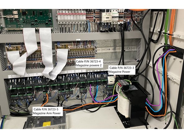
Install cable 36723-5 to Q23 and wire as shown in the wiring chart in Photo 2. Then route it out through the electrical cabinet and join it with the cables from the previous step. See Photo 3 for cable routing.
-
Install cable 36723-4 to K31 and wire as shown in the wiring chart in Photo 1. Then route it out through the electrical cabinet and join it with the cables from the previous step. See Photo 3 for cable routing.
-
Install cable 36723-3 to K32 and wire as shown in the wiring chart in Photo 1. Then route it out through the electrical cabinet and join it with the cables from the previous step. See Photo 3 for cable routing.
-
Install each of the last three (3) cables into their own conduit.
-
-
-
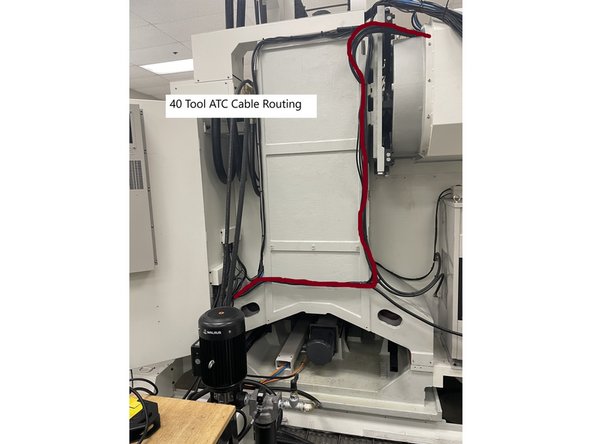
Route the ATC cables from the electrical cabinet up to the ATC cable junction box. See Photo 1 for cable routing path.
-
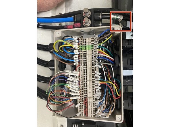
Install the ATC cables from the electrical cabinet into the cable junction Box mounted on the ATC, as shown in Photo 2.
-
Wire the cables to the terminal block in the cable junction box using the wiring chart in Photo 3.
-
-
-
Looking in from the top of the ATC assembly:
-
Install the blue air line to the fitting labeled up and the black line to the fitting labeled down. See Photo 1
-
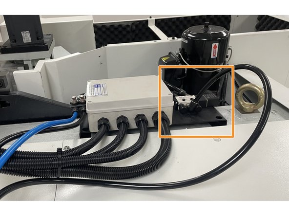
Install the longer black air line to the elbow fitting on the solenoid valve on the opposite side of the cable junction box. See Photo 2
-
Once the air lines have been connected reconnect power to machine and turn on
-
-
-
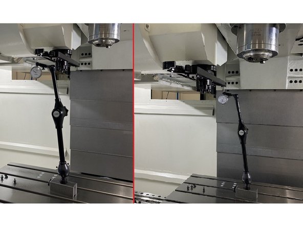
To level the ATC arm power up the machine and position the Z axis at its maximum Z up travel.
-
Set up a plunger indicator and large mag base to measure the ends of the ATC arm. Zero the indicator at one end of the ATC arm and then move in the X Axis off of the arm and then in the Y Axis to the other end of the ATC arm and back onto the arm in the X. Record the measurement.
-
To adjust the level of the ATC Arm crack loose and then snug the (8) M16 ATC mounting screws.
-
Next by a combination of loosening and tightening the (4) push screws (levelers) attached to the adapter plate adjust the level of the ATC Arm to 0.006" or less from end to end. Leave screws snug for now.
-
-
-
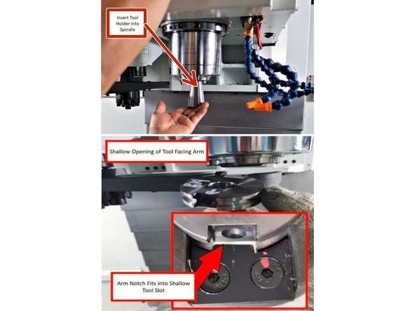
Now that the ATC Arm is level in the Y Axis we need to align the ATC Arm to the spindle. Before proceeding verify that the Z Axis is still at the upper soft limit.
-
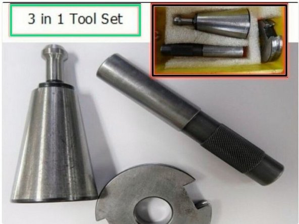
First locate the 3 piece alignment tool set.
-
Next remove both drive dogs from the spindle.
-
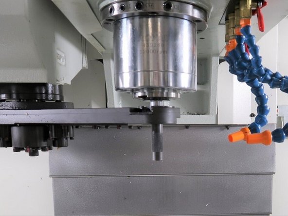
Install the 40 Taper Tool Holder from the 3 piece alignment tool kit into the spindle. Then install the disk tool into the ATC Arm with shallow side of the ring tool into the targeting key of the ATC Arm. See Photo 3
-
-
-
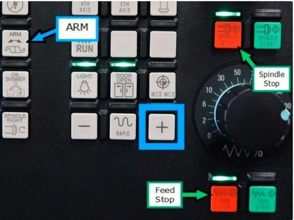
Enter ATC or Swivel Head Service Mode by pressing and holding the red "SPINDLE STOP" button while pressing the red "FEED STOP" button three times quickly.
-
If done correctly the green LED above "FEED STOP" will blink and a message will show stating that the ATC or Swivel Head Service Mode is on.
-
ATC or Swivel Head Service Mode disables any safety feature preventing the arm to crash. Use caution while operating in this mode. Make sure arm has a clear path before moving.
-
Ensuring no collision will occur, press and hold the "ARM" button and the "+" button together until the arm stops moving and is positioned under the spindle.
-
-
-
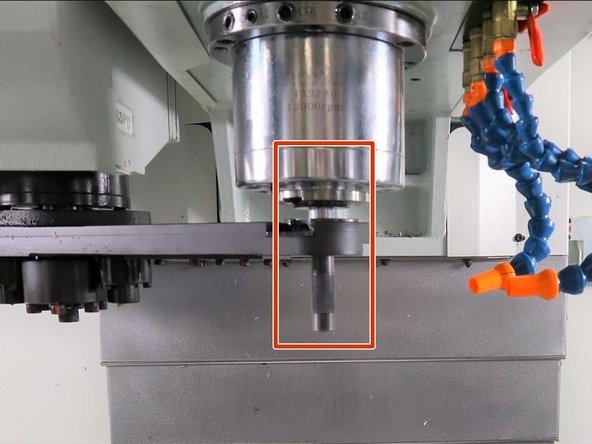
Using the push and pull screws for the X and Y ATC movement, position the arm so the alignment tool holder and alignment disk are concentric and the alignment bar can slide between the two easily.
-
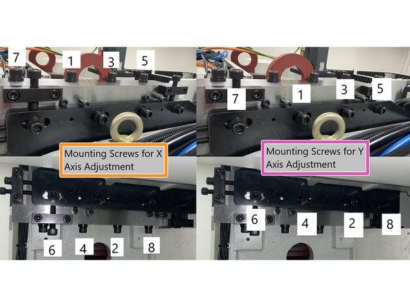
Start with the Y axis adjustment. First tighten the eight (8) X Axis mounting screws, then loosen and snug the Y Axis mounting screws. Then push or pull the Y Axis to where it is looks to be in alignment with the spindle. Tighten the screws. See Photo 2
-
Now loosen the X Axis mounting screws and snug them and using the push pull adjustment screws for the X Axis, adjust the ATC to where the X Axis is aligned with the spindle. You will probably need to go back and forth a few times loosening and tightening the X and Y mounting screws and adjusting the ATC until it is aligned. See Photo 2
-
Don't leave both X and Y axis mounting screws loose (snug) at the same time during alignments because when you torque the screws at the end the ATC alignment can change considerably when torqued.
-
Once the alignment is good rotate the arm 180 degrees and check it again. You may need to find a best fit between both ends of the arm for optimal tool change performance.
-
After the ATC has been aligned the ATC mounting screws need to be torqued. Start with the M16 screws for the X Axis mounting brackets. Torque them to 150ft-lbs, in a crossing pattern from the center out. See Photo 3.
-
Then torque the M16 screws on the Y Axis mounting brackets. Torque them to 150ft-lbs. Same as the X in a crossing pattern from the center out. See Photo 3
-
Once all of the screws are torqued verify the ATC alignment didn't change. If it did go back to the beginning of this step and repeat.
-
-
-
Once the ATC has been aligned the orientation angle and tool change height need to be adjusted. Follow VMCsi - Set Orientation Angle & Tool Change Height procedure.(VMCsi - Set Orientation Angle & Tool Change Height )
-
Once the orientation angle and tool change height has been set, reinstall the spindle drive dogs to the spindle.
-
On machines equipped with a black drive dog install it in the spindle facing towards the ATC Arm.
-
-
-
Once the size of the ATC has been changed the tool table will need to be updated to show the 40 tool positions corresponding to the new ATC.
-
To update the tool table:
-
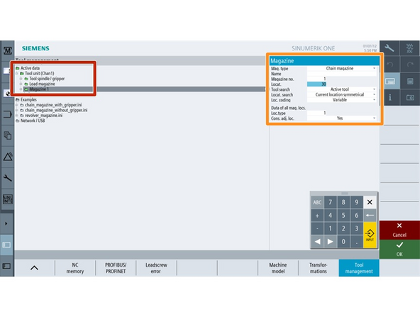
Press E-Stop, with the manufacturer password set, go to setup -> NC -> Tool Management -> Active Data -> Tool Unit (Chan1) and double click Magazine 1.
-
Update Locat. field to the value that corresponds with the number of positions on the ATC assembly that has been installed and press Ok to confirm.
-
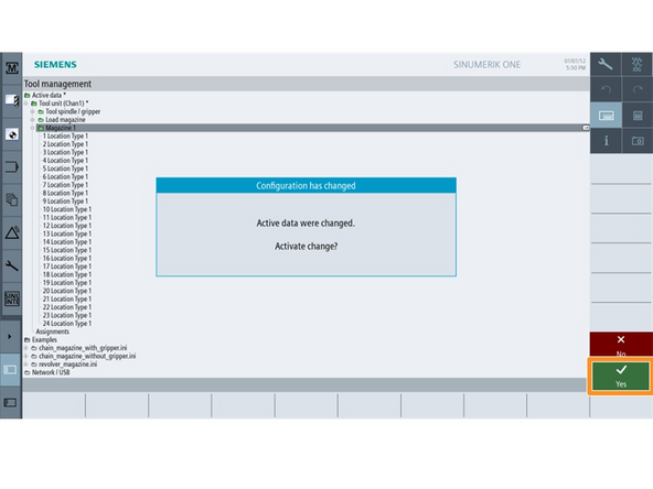
When leaving the Tool Management screen a message will appear to activate the changes, press Yes to confirm.
-
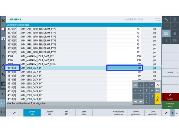
Go to Setup -> Machine Data -> General MD and search for parameter MD 14510[0]
-
Update MD 14510[0] to the value that corresponds with the number of positions on the ATC assembly that has been installed.
-
Power cycle the machine to save the new settings for the number of tools on the ATC assembly..
-
-
-
The new ATC magazine may need referencing to find its home position.
-
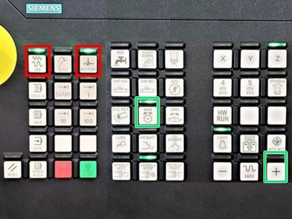
To reference the ATC magazine press both the JOG and REF. POINT buttons on the MCP.
-
Press and hold the MAG button and then press the "+" button on the MCP to reference the ATC magazine.
-
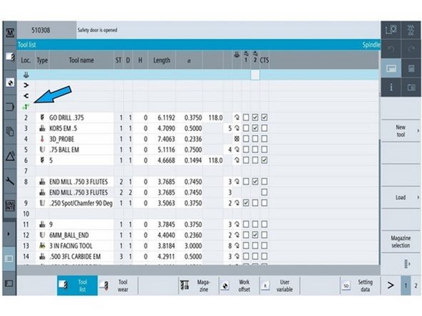
Check position of the green arrow in the tool table matches the pot number which is in tool change position in the ATC magazine.
-
If pot number in the tool change position on the magazine does not match the tool with the green arrow on the tool table perform tool change for the first pocket to sync the ATC magazine with the machine control.
-
Run a few manual tool changes on the machine control to verify everything is correctly positioned.
-