Introduction
Replace the ATC arm on any VMCsi: a damaged arm with a new arm of the same type, or the standard CAT40 arm with the BT40 Option arm (P/N 34085).
Required tool: 3-in-1 ATC Arm Tool Set.
The targeting keys on the VMC7si and VMC10si arms are different from the VMC12si and VMC14si arms. See Step 1.
Tools
Parts
No parts specified.
-
-
Each ATC arm has a targeting key on the tool finger at each end.
-
The key lines up with the spindle dogs and the indexing lugs on the ATC pot, so the tool holder is oriented correctly for the tool change.
-
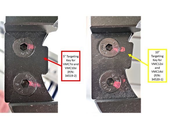
The key differs by model (see image):
-
VMC7si and VMC10si: 5° targeting key, P/N 34519-2.
-
VMC12si and VMC14si: 10° targeting key, P/N 34520-1.
-
Check that the new arm has the correct targeting key for this model before you start.
-
-
-
ATC or Swivel Head Service Mode gives manual control of the tool changer with all ATC safeties off. Without a full understanding of the ATC and tool change functions, you can damage the mill or injure yourself.
-
Service Mode is used for maintenance, and to recover the ATC from an error state.
-
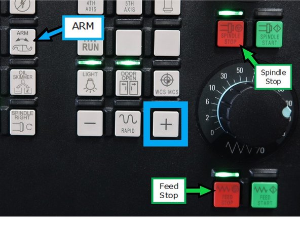
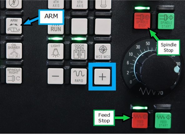
To enter Service Mode: press and hold [SPINDLE STOP], then press [FEED STOP] three times quickly. The green LED above [FEED STOP] blinks about once per second.
-
To exit Service Mode: press [RESET] on the MCP.
-
For more on Service Mode, see Section 4.0 Automatic Tool Changer, Sub 4.3 ATC or Swivel Head Service Mode in the TRAK VMCsi Siemens SINUMERIK CNC - Safety, Installation, Maintenance, Service and Parts List (34104).
-
-
-
Steps 3 and 4 are only for an arm that is undamaged and can be operated safely. A tool change moves the spindle to tool change height and leaves the arm at home.
-
If the arm is damaged, skip to Step 5.
-
To do a tool change:
-
Press [JOG] on the Machine Control Panel (MCP).
-
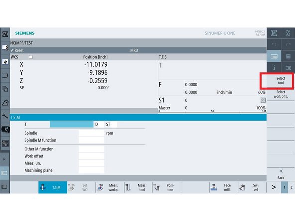
On the touchscreen, (1) press the [Machine] shortcut key in the left-hand corner, then (2) press [T, S, M].
-
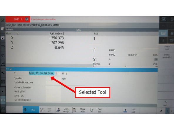
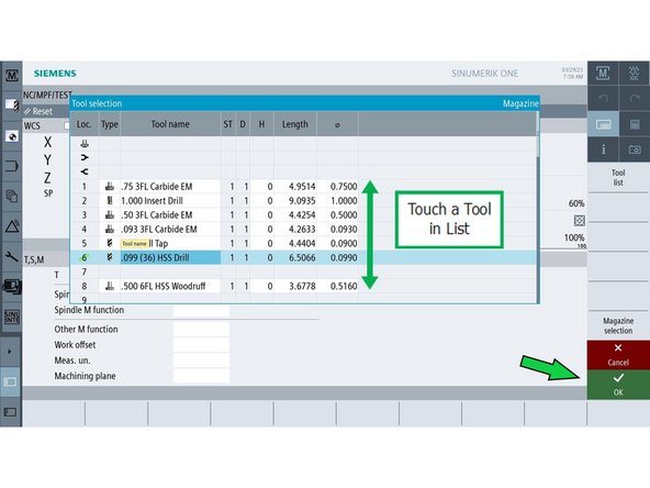
(3) Click the T field, then (4) press [Select tool].
-
The "Tool selection" window opens. Scroll through the list and select the tool to load.
-
-
-
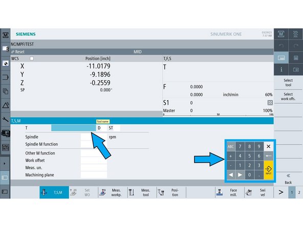
The selected tool shows in the T field.
-
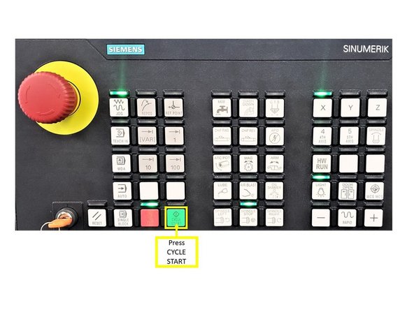
Press [CYCLE START] on the MCP.
-
When the tool change finishes, the arm is at home and the spindle is at tool change height. Skip to Step 9.
-
-
-
Steps 5 to 8 are required only if a tool change was not possible in Steps 3 and 4.
-
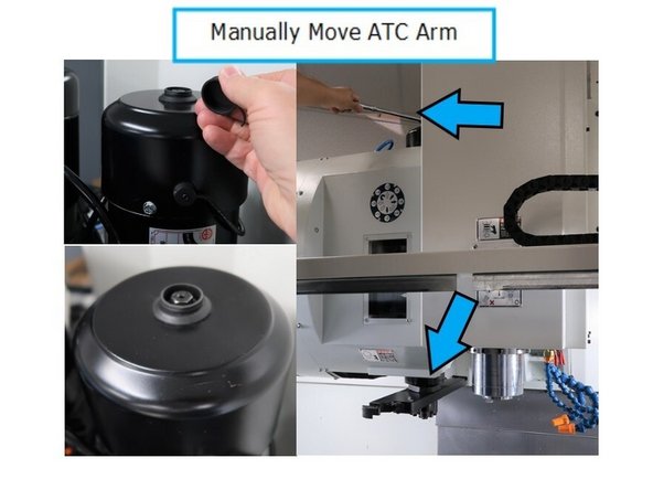
A crashed arm can be moved by hand with a 12 mm socket and 3/8 in drive ratchet on top of the ATC motor. If possible, jog Z to the top of its travel first. If not, rotate the arm until Z can safely move to the top.
-
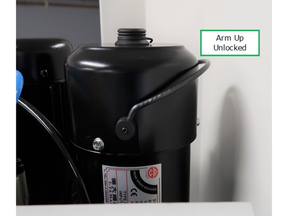
Release the motor brake by lifting the brake arm up from its down position. A rag between the brake arm and the motor body holds it up. Do not use excessive force.
-
Remove the bolt cover. Turn the 12 mm socket clockwise until the arm reaches home.
-
If the arm is still in the crashed position, turn the socket counterclockwise first to back the arm off any stuck tools.
-
The motor has an 8:1 reduction. It takes several turns before the arm moves.
-
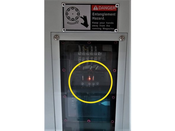
Rotate until the center LED lights; the arm is at home. Lower the brake lever to lock the arm, then replace the cap.
-
Also see VMCsi ATC Arm Manual Movement.
-
-
-
All ATC safeties are off in Service Mode and the arm swings at speed. Stay clear of the arm path.
-
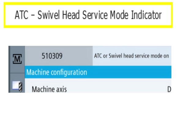
Press and hold [SPINDLE STOP], then press [FEED STOP] three times quickly. The green LED above [FEED STOP] blinks, and a Service Mode message shows at the top of the touchscreen.
-
The LED should blink about once per second. Repeating the pattern enters other service modes, which blink faster. Use only the slowest. If you enter the wrong mode, press [RESET] and enter the pattern once.
-
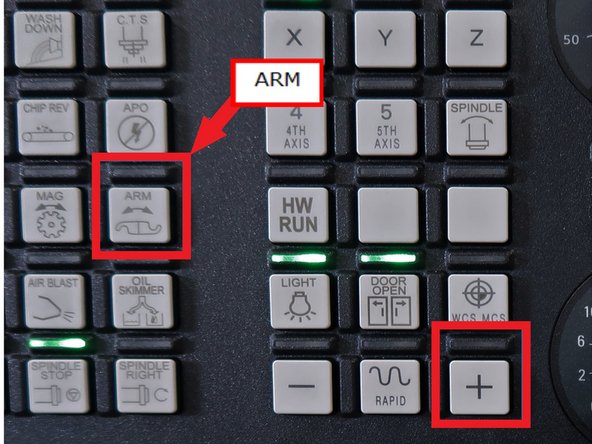
Press and hold [ARM], then press and hold [+] to move the arm under the spindle. Hold [+] until the arm is fully in tool change position. A quick release does not finish the move.
-
If the arm stops short, press and hold [ARM] and [-] to return it home, then press and hold [ARM] and [+] again.
-
-
-
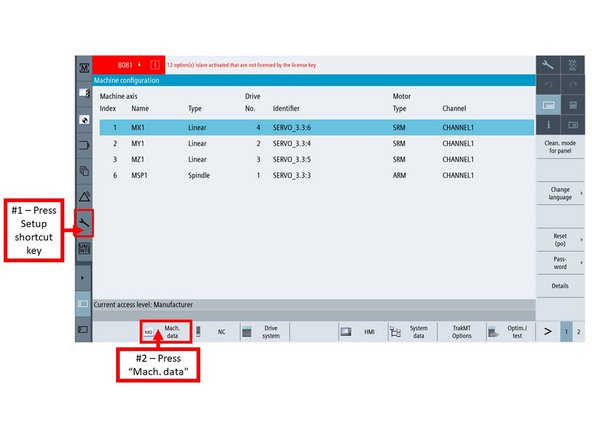
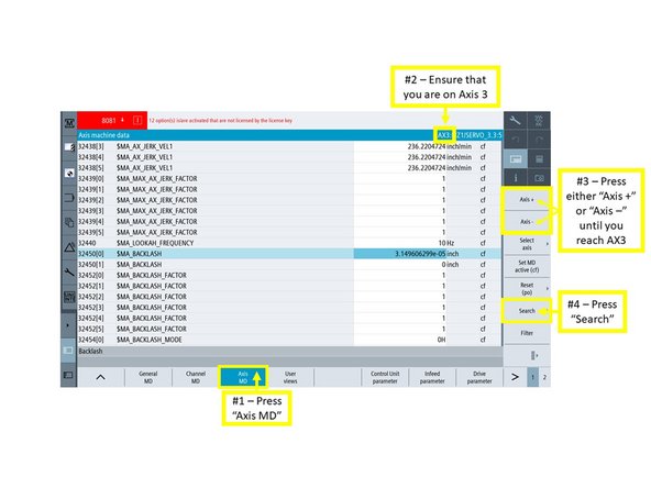
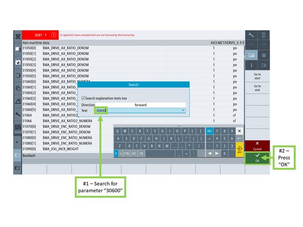
MD30600[0] on the Z axis holds the spindle tool change height.
-
(1) Press the [Setup] shortcut key on the left bar, then (2) press [Mach. Data].
-
(1) Press [Axis MD]. The "Axis machine data" window opens.
-
(2) Confirm the window shows AX3 (Z axis). (3) If not, press [Axis +] or [Axis -] until it does.
-
(4) Press [Search].
-
(1) Enter 30600, then (2) press [OK].
-
-
-
The search lands on MD30600[0]. Write down the value.
-
(1) Press the [Machine] shortcut key, then (2) press [Act. values Machine].
-
Keep [Act. values Machine] highlighted during the next bullet.
-
(3) Jog Z to the MD30600[0] value. The spindle is now at tool change height.
-
Press and hold [ARM] and [-] until the arm returns home.
-
Press [RESET] on the MCP to exit Service Mode.
-
-
-
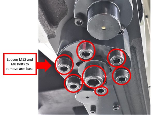
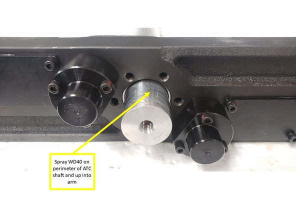
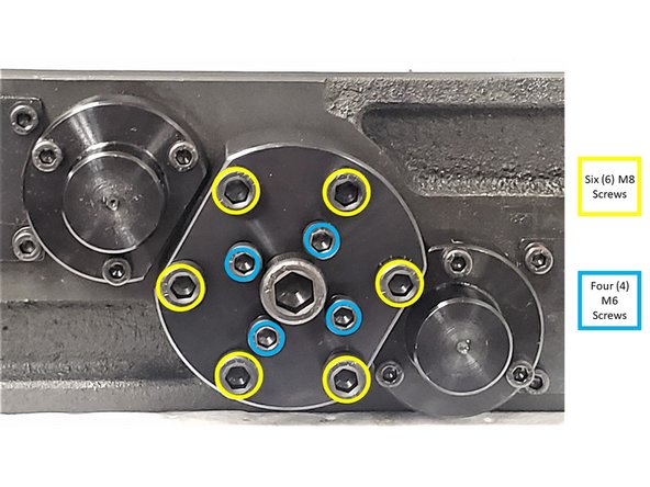
Remove the center M12 bolt and six (6) M8 bolts from the arm base, then remove the base from the ATC shaft. Spray WD-40 around the shaft and up into the arm.
-
Reinstall the base and loosely thread in the M12 bolt without its washer, so it catches the arm when it comes free.
-
-
-
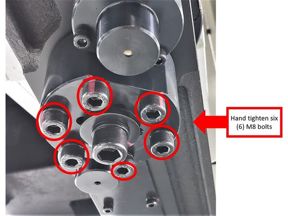
Work the arm down the shaft by alternating the six (6) M8 screws and four (4) M6 30 to 40 mm SHCS in the arm base (see image):
-
Thread the M8 screws 2 to 3 turns into the arm base.
-
Thread the M6 screws into the arm base until they touch the bottom of the ATC shaft. They act as jack screws to push the arm off the shaft.
-
Tighten the M8 screws a couple of turns in a cross pattern. This pulls the arm down toward the base. Do not let the base re-engage the taper lock rings.
-
Loosen the M8 screws. The base drops further, giving room to extend the M6 screws.
-
Tighten the M6 screws in a cross pattern until they touch the bottom of the shaft again.
-
Repeat, always in a cross pattern, until the arm turns freely at the bottom of the shaft.
-
-
-
The arm weighs about 25 to 30 lb. Lowering it is easier sitting on the table. Press [E-STOP] before climbing onto the table.
-
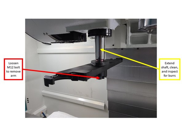
When the arm turns freely at the bottom of the shaft (see image), remove the M12 bolt and lower the arm off by hand.
-
If the arm does not come free, rotate it back and forth while pulling down.
-
Release [E-STOP] and enter Service Mode. Fully extend the shaft, inspect it for burrs, and stone any rough edges from removal. Wipe the shaft with a clean rag.
-
To extend the shaft: press and hold [ARM] and [+] until the arm reaches tool change position. Press the green unclamp button on the spindle, then hold [ARM] and bump [+] until the shaft lowers.
-
-
-
Required only when fitting the BT40 Option arm (P/N 34085) in place of the standard CAT40 arm. For a same-type replacement, skip to Step 13.
-
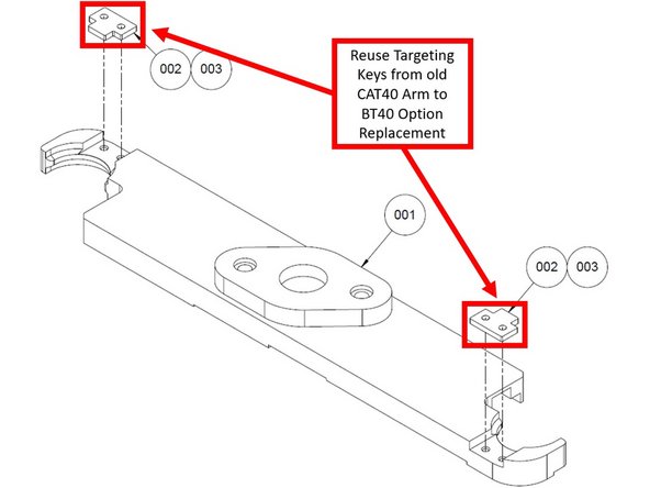
Remove the targeting keys from the old CAT40 arm and install them on the new BT40 arm.
-
The key type depends on the model. See Step 1.
-
Return the old CAT40 arm to the warehouse to stock as P/N 34519-1.
-
-
-
Enable the spindle on the MCP.
-
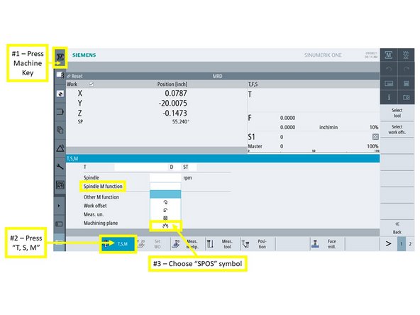
(1) Press the [Machine] shortcut key at the top left, then (2) press [T, S, M].
-
(3) In the Spindle M function field, select the last option, SPOS.
-
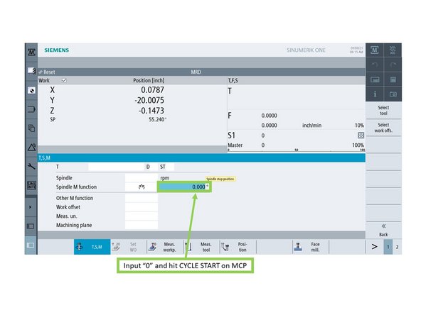
In the Spindle stop position field, enter 0, then press [CYCLE START].
-
The spindle dogs orient to the tool change angle for the new arm.
-
-
-
Enter Service Mode.
-
Use the arm jog buttons to move the shaft fully to tool change position.
-
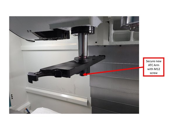
Lift the new arm onto the shaft. Loosely thread in the M12 SHCS and washer. The arm should turn freely on the shaft.
-
If the M12 SHCS will not start, leave the washer off and work the arm up the shaft. Add the washer when you torque the M12.
-
The arm turns freely on the shaft now. Keep it clear of the spindle and the ATC pot during the next steps.
-
-
-
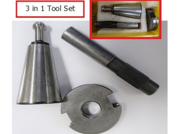
The 3-in-1 alignment tool sets the arm position on the shaft.
-
Gather the 3-in-1 Tool Set: tool holder, disc and alignment bar.
-
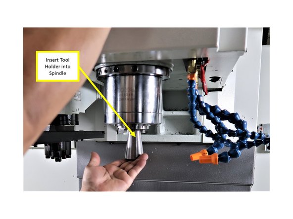
Insert the 3-in-1 tool holder (CAT40/BT40 taper) into the spindle.
-
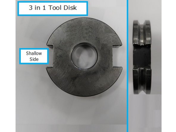
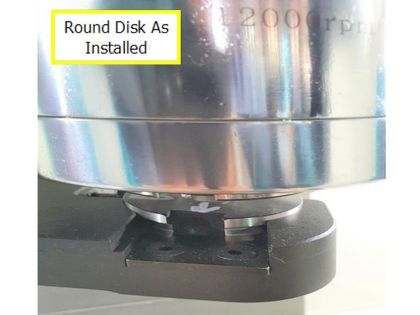
Insert the round disc into the arm. One side is deeper than the other; orient it as shown.
-
-
-
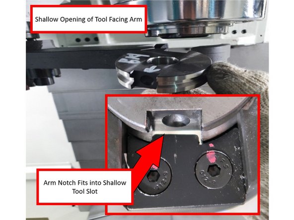
With the shaft at tool change position, the arm plunger is compressed, so the disc drops in easily.
-
The notch on the arm (inset) must sit in the shallow slot of the disc.
-
Close-up: the shallow side of the disc installed in the arm, under the spindle.
-
-
-
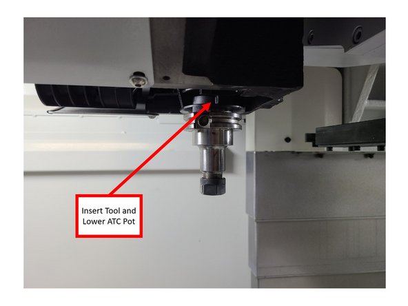
Insert a tool into the ATC pot with the deep notch toward the pot targeting key, then lower the pot. Keep the arm clear while the pot lowers.
-
If the shallow notch faces the key, the holder does not seat fully in the pot and the arm height will be wrong.
-
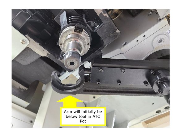
Rotate the arm by hand so its tool finger sits below the tool in the pot. Start with the arm lower than the tool.
-
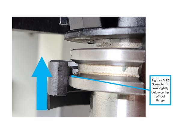
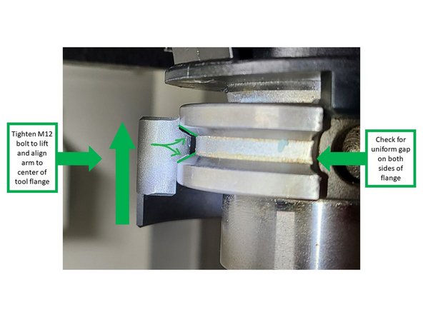
Tighten the M12 bolt to lift the arm toward the tool flange.
-
Stop when the tool finger is just below the center of the flange (see image).
-
-
-
Snug the M8 screws around the M12 so the arm is firm on the shaft. Snug only until the base starts to touch the taper lock rings; the arm must still rotate.
-
Keep tightening the M12 bolt until the arm engages the tool flange smoothly, with an even gap on both sides.
-
A flashlight shows the gap between the flange and the arm.
-
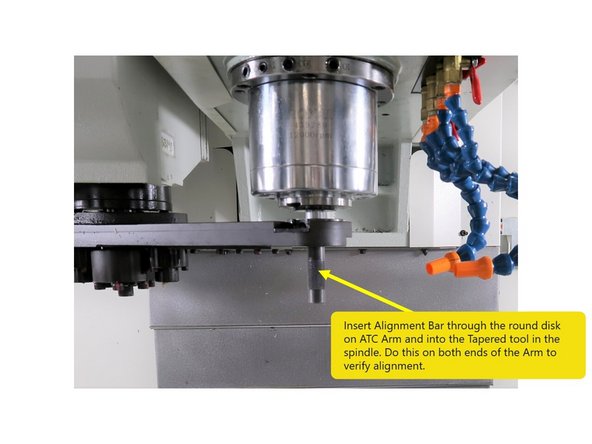
With the arm at height, rotated and fully engaged with the pot, insert the 3-in-1 alignment bar through the disc and into the spindle (see image). Check both ends of the arm.
-
Tighten the M8 bolts so the arm no longer turns on the shaft.
-
Rotate the arm clear of the tool holder. Press and hold [ARM] and [-] to return the arm home.
-
Remove the tools from the spindle and arm, and raise the pot.
-
-
-
Start with the arm at home.
-
In Service Mode, press and hold [ARM], then press and hold [+] to move the arm under the spindle.
-
-
-
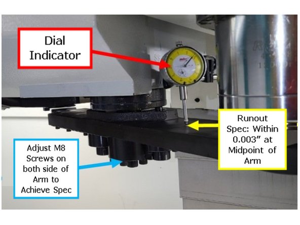
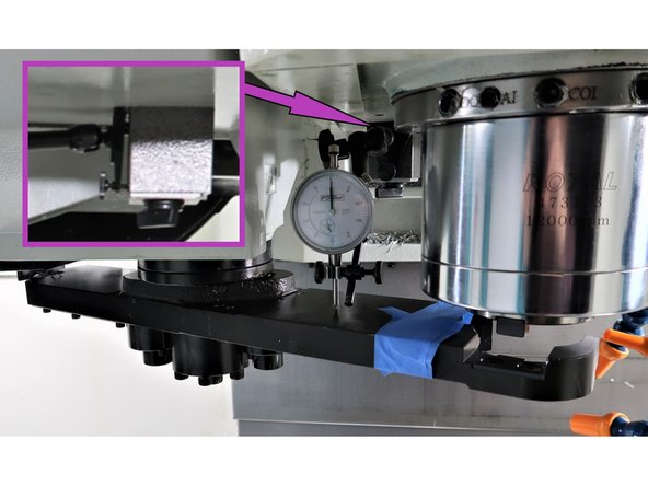
Mount a dial indicator with a mag base on the ram casting. Center the needle on the arm halfway between the shaft and the tool finger.
-
Inset: mag base location on the ram casting, seen from the right side of the mill.
-
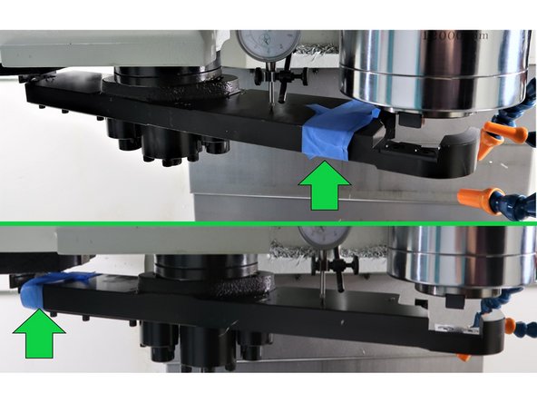
Mark the arm starting position with tape. Leveling takes several moves back and forth, and the tape shows which way to return.
-
To move the arm to the other side, press and hold [SPINDLE UNCLAMP] for 3 to 5 seconds, then press and hold [ARM] and [+]. To go back, press and hold [ARM] and [-].
-
After the first move you do not need to hold [SPINDLE UNCLAMP] again.
-
If the arm returns home by mistake, remove the indicator and mag base before moving it under the spindle again. From home the arm swings without dropping first and will hit the indicator.
-
Indicate the midpoint of each side of the arm (between the shaft and the tool finger). Level must be within 0.003 in.
-
If out of spec, adjust the M8 screws on each side. Tightening one side lowers that side and raises the other.
-
-
-
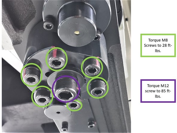
Once level, torque the M8 screws in a cross pattern to 28 ft-lb. Then tighten the M12 a few turns and recheck level. Smaller steps give a better result.
-
To hold level, a few M8 screws may need slightly more than 28 ft-lb. Do not exceed 35 ft-lb.
-
Install the M12 washer if you left it off, then torque the M12 bolt to 85 ft-lb.
-
Recheck level.
-
If it is out of spec, readjust the M8 screws and recheck. Do not run tool changes until it is level.
-
-
-
Press [RESET] on the MCP to exit Service Mode.
-
Load a tool: press [T, S, M], then press [Select tool].
-
Select any tool in the carousel list, press [OK], then press [CYCLE START].
-
Return to T0: touch the T field, enter 0, press [INPUT], then press [CYCLE START].
-
Do several tool changes. There should be no harsh noises.
-
If alignment is off, tools can drop or eject. If you hear binding or a tool drops, stop and go back to Step 17.
-





Team