-
-
Press E-Stop, then turn off the machine by turning the breaker on the electric panel cover counterclockwise.
-
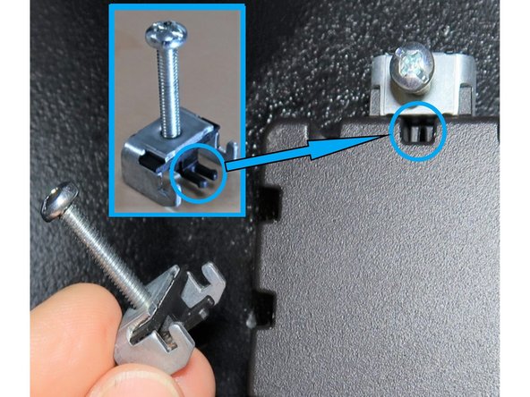
Remove the rear pendant cover by loosening all eight 6 mm hex screws. Refer to the inset photo showing the slots for the screws. You can easily lift off the rear panel cover by clearing the slots and then find a safe place to store it.
-
The pendant back cover is heavy.
-
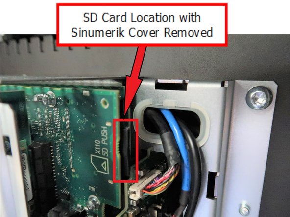
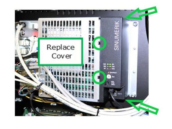
Press the top, bottom, and side tabs of the plastic cover on the back of PPU1740, as indicated by the arrows, to release the cover. The SD card is located in the top area under the circuit board.
-
-
-
The SD card is located on the top right behind the plastic cover.
-
Gently press the SD card inward to unlock and remove it.
-
-
-
Remove each wired connection as listed. Label the wires if needed to ensure clarity for reattachment.
-
Remove wires (1) & (2) by pressing the lock. Press the lock to disconnect the LAN connection (3). For the two USB cables (4), ensure the front cable reconnects to the front USB port and the back cable to the back port after replacing the PPU.
-
Cables (5), (6), and (7) are pressed into place; squeeze both ends carefully to remove them from the PPU. These similar cables must be returned to their correct locations. The green cable 11 also requires a squeeze on both ends to remove and may not have a label.
-
(5) - X 122 (6)- X 132 (7) - X 242 (11) - X 143
-
Loosen the screw for (8) and remove the ground wire with two cables. Loosen the screw for (9) and remove the cable. For (10), use a jeweler’s flat blade screwdriver to release the X1 cable. Remove the two ground cables (12).
-
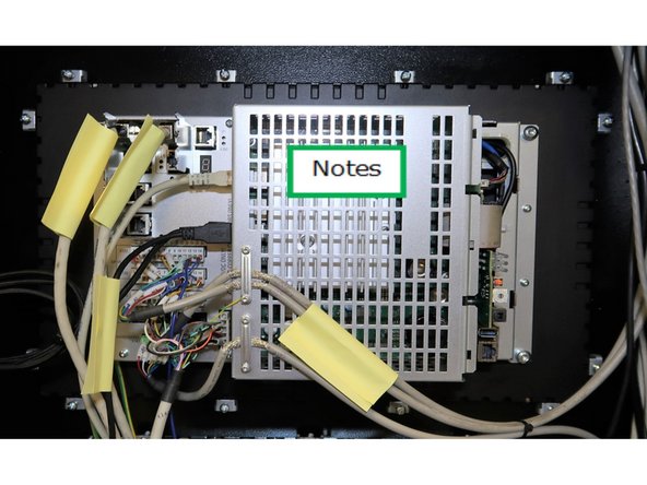
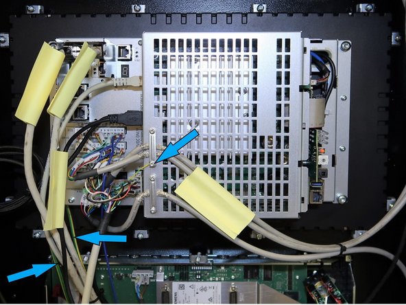
Refer to the labeled picture for added notes on wire locations. Remove all wires from the PPU as indicated.
-
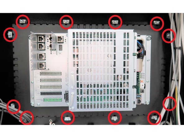
Clamps around the PPU perimeter secure it to a bracket on the pendant. When reinstalling, ensure each screw tightens securely, locking the plastic arm inside the PPU groove.
-
-
-
Secure the pendant to prevent it from falling. Loosen the twelve screws on the clamps securing the PPU to the pendant frame. Remove the clamps and carefully lift out the original PPU.
-
Unpack the new PPU and secure it in place using the twelve clamps. Replace the plastic cover that was removed to access the SD card on the previous PPU. Use the new PPU’s packaging to safely return the old PPU.
-
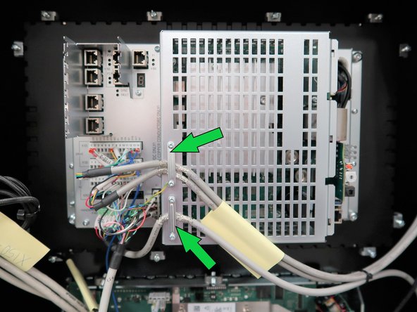
Begin attaching wires from bottom up, ensuring each connector is properly seated. Refer to the photo for one section reattached. Use the brackets for strain relief on the wires.
-
Verify all connections are secure, especially the three ground wires, and remove any labels used for notes.
-
-
-
Remove the plastic cover from the new PPU as shown in Step 5.
-
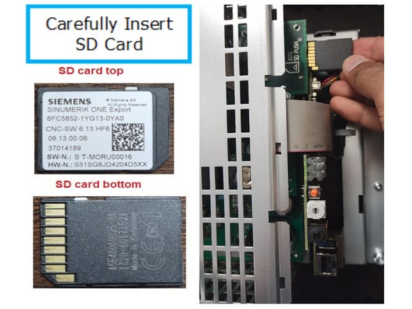
Insert the original SD card into the new PPU and press until it locks in place.
-
Carefully align the side, top, and bottom tabs, then push the cover into place.
-
Rotate the center arrow on the NCK switch to point to "0".
-
Replace the rear metal cover of the pendant, and use an allen key to fasten it securely.
-
-
-
Once the machine finishes restoring the archive, ensure the [E-Stop] is pressed.
-
Turn the power off and wait a minute before turning it back on.
-
If the machine gives an error on the power cycle, see the next step.
-
-
-
After the archive is loaded, if the control shows alarms 3000 - PLC sign of life monitoring or 2001 - PLC has not started up, locate the PLC switch at the bottom right side on the back of the PPU.
-
Flip the switch to [STOP] from [RUN] and then back to [RUN] again.
-
Power cycle the machine. Afterwards, the PLC related alarms should clear.
-
Almost done!
Finish Line




![Once the machine finishes restoring the archive, ensure the [E-Stop] is pressed.](https://d3t0tbmlie281e.cloudfront.net/igi/trakmtsupport/PbHX3qeeAECuoTsq.medium)
