
-
-
Confirm the machine is factory-prepared for the 4th Axis option.
-
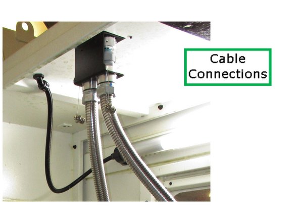
Locate the ceiling connectors inside the enclosure on the right side of the spindle.
-
Remove the required 4th Axis knock-outs from the machine plate, if still covered.
-
-
-
Safety: Use a lifting device. The 4th Axis is heavy.
-
Power off the machine before installing the 4th Axis.
-
Install base key (Item 011) and hardware (Item 034, 2X) under the 4th Axis.
-
Lift from the designated lift point and place on the right side of the table.
-
Install T-bolts, clamping blocks, and flange nuts loosely (do not tighten).
-
-
-
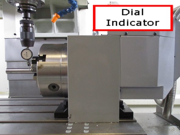
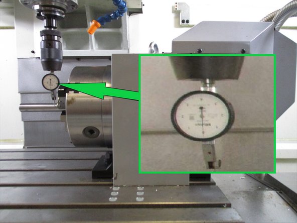
Mount a dial indicator on the spindle.
-
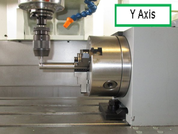
Load straight stock in the 4th Axis chuck.
-
Ensure stock is straight and seated properly before aligning.
-
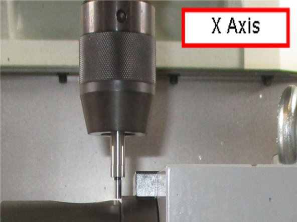
Sweep the OD of the stock along the X-axis.
-
Adjust the 4th Axis until the indicator reading is consistent across the sweep.
-
Tighten all mounting hardware once aligned.
-
-
-
Using an Edge Finder: Load known diameter stock in the 4th Axis.
-
X-Axis: Touch off the face of the 4th Axis faceplate (behind the chuck). Subtract half the edge finder diameter. Record as MX1.
-
Y-Axis: Touch off the OD of the stock. Subtract half the stock diameter. Record as MY1.
-
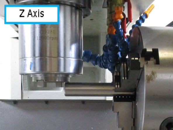
Z-Axis: Bring the spindle nose to the top of the stock. Add half the stock diameter. Record as MZ1.
-
Using a Renishaw Probe: Load known diameter stock in the 4th Axis.
-
X-Axis: Probe the 4th Axis faceplate (behind the chuck) and record as MX1.
-
Y-Axis: Probe both sides of the stock OD to calculate centerline and record as MY1.
-
Z-Axis: Probe the top of the stock. Add half the stock diameter to move from the surface to the centerline of rotation. Record as MZ1.
-
-
-
This step records the three axis values you noted. Later on in this process you will be able to start or stop the 4th axis.
-
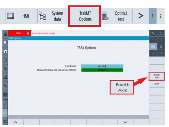
To access the axis information screen, at the upper right corner of the display, press [M], press “SETUP” from the left VSK menu bar then press “TrakMT Options” from the HSK as shown along the top of the image.
-
Press E-Stop
-
The TRAK Options screen will display the current status of the 4th Axis as well as the Advanced Surface and Top Surface (AS/TS) options. Press “Fourth Axis” from the right VSK
-
Caution: The screen will take any value, so double check your inputs in the next step.
-
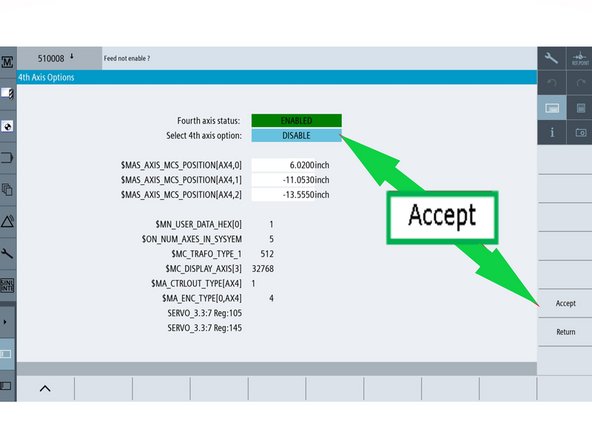
You will now see the 4th Axis Options screen. The Fourth axis Enable/Disable status is on the first line. The 4th Axis should be disabled at this point. Set X/Y/Z position using the values you noted above to record the 4th Axis location on the table.
-
Highlight each axis one at a time and use the pop-up keypad to enter inputs for the three Axis then press “Accept” and “Return”.
-
The 4th Axis encoder and power cables should be connected to the ceiling connectors in the machine before enabling the option. When removing the 4th Axis from the mill, disconnect the cables before disabling the 4th Axis software.
-
-
-
Reboot machine to activate the previous settings.
-
Once the 4th Axis Option is installed in your machine, it is available to use whenever it is needed.
-
To change status of the 4th Axis, E-Stop Machine:
-
Enable 4th Axis:
-
When either installing the option for the first time or reinstalling, the encoder and power cables need to be connected to the two connectors on the inside ceiling of the machine before enabling the 4th axis.
-
Disable 4th Axis:
-
The encoder and power cables need to be disconnected before disabling the 4th axis.
-
Once the cables are ready for the status change, proceed to the next step.
-
-
-
To access the axis information screen, at the upper left corner of the display, press [M], press “SETUP” from the left VSK menu bar then press “TrakMT Options” from the HSK as shown along the top of the image.
-
The TRAK Options screen will display the current status of the 4th Axis as well as the Advanced Surface and Top Surface (AS/TS) options. Press “Fourth Axis” from the right VSK
-
The 4th Axis status is displayed on the top line of the 4th Axis Option screen. To change the status, press the second line which displays both “Enable” and “Disable” from the drop down menu. Press your selection and then “Accept”.
-
Reboot and release E-Stop. When the mill powers up, the new configuration will be in place.
-
-
-
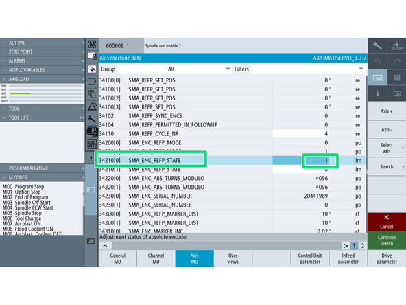
Go to [Setup]→ [Mach. data] → [Axis MD] → [Select Axis] →[AX4:MA1]
-
[Search] for 34210.
-
On the Axis MD window, confirm that you are under AX4:MA1.
-
Turn on the [JOG], [REF. POINT], and [4] buttons on the MCP.
-
Change Parameter 34210 to "1"
-
Parameter 34210 set to 1 means the encoder is ready to establish a new reference, indicating the manual setup state.
-
Press the "[+]" button on the MCP. The value for Parameter 34210[0] should change from "1" to "2" automatically.
-
The changing of the value to "2" means that the referencing process is complete for that particular axis.
-
-
-
Press the [+] key on the MCP while still in parameter window. This should change the Parameter value to 2.
-
Going back to Machine [M] screen should show the circle next to MA1, confirming that the axis has been referenced succesffully
-
This axis must be re-referenced any time that parameter 34210[0] is cleared back to 0. One of the ways this can happen is when loading an archive file from one machine to another.
-
-
-
This alignment and location parts of the procedure has to be redone for the X & Y axis each time the 4th axis has been moved or reinstalled.
-


![To access the axis information screen, at the upper right corner of the display, press [M], press “SETUP” from the left VSK menu bar then press “TrakMT Options” from the HSK as shown along the top of the image.](https://d3t0tbmlie281e.cloudfront.net/igi/trakmtsupport/avGG2YhLAu3givW5.medium)
![To access the axis information screen, at the upper left corner of the display, press [M], press “SETUP” from the left VSK menu bar then press “TrakMT Options” from the HSK as shown along the top of the image.](https://d3t0tbmlie281e.cloudfront.net/igi/trakmtsupport/nFYRJ3C3KDlTYnSm.medium)
![Go to [Setup]→ [Mach. data] → [Axis MD] → [Select Axis] →[AX4:MA1]](https://d3t0tbmlie281e.cloudfront.net/igi/trakmtsupport/QNQZREQjjyMOEudK.medium)
![[Search] for 34210.](https://d3t0tbmlie281e.cloudfront.net/igi/trakmtsupport/BUVKUKvMOuULx6jf.medium)
![Press the [+] key on the MCP while still in parameter window. This should change the Parameter value to 2.](https://d3t0tbmlie281e.cloudfront.net/igi/trakmtsupport/twgIAftf1OYF4p5U.medium)
![Going back to Machine [M] screen should show the circle next to MA1, confirming that the axis has been referenced succesffully](https://d3t0tbmlie281e.cloudfront.net/igi/trakmtsupport/J5XcJfYYSbDB4ZAi.medium)