Parts
No parts specified.
-
-
If at any time a new X, Y, or Z offset is changed in the [TrakMT Options] screen, or if X, Y, or Z axis is re-referenced, this entire calibration procedure must be completed again.
-
This process verifies the control’s internal kinematic model matches the machine’s real geometry.
-
(Step 7) 5-Axis Kinematic Chain Setup – The 5AXISKINCHAIN program builds the geometry framework that links the rotary axes (A, C) to the linear axes (X, Y, Z).
-
(Step 8) Horizontal & Vertical Measuring – The calibration sphere is probed in both flat and upright positions to compare results for alignment.
-
(Step 11) Skew Check – Compares both measurements to ensure the trunnion is aligned within 0.008".
-
(Step 12) Correction – The KIN_CORRECT program updates the kinematic model with measured data. (This is the actual calibration point)
-
(Step 14) Verification – The process is repeated to confirm the corrections are applied and alignment is within spec.
-
-
-
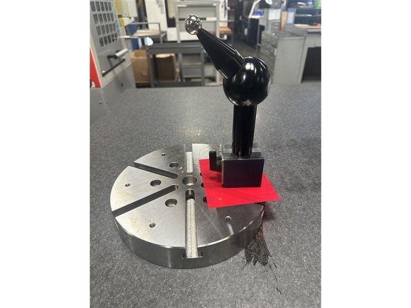
Always place a plastic shim between the calibration sphere base and the trunnion platter.
-
When removing, disable the magnet first, then lift the sphere straight up
-
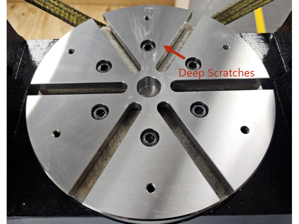
Never drag the base across the platter surface.
-
-
-
VMCsi 7 & 10 use 50mm Probe Stylus for Trunnion Calibration.
-
-
If probe calibration has not been completed, follow the VMCsi Probe Part Option guide to complete the probe setup. Perform the following steps:
-
Stylus Runout Adjustment – Ensure the probe stylus is properly aligned.
-
Calib. Tool: Set Work Offset – Set the correct work offset using the calibration tool.
-
Calibrate Probe Length – Measure accurate probe length.
-
Calibrate Probe Diameter – Measure accurate probe diameter.
-
-
-
Set the A-Axis and C-Axis positions to 0.
-
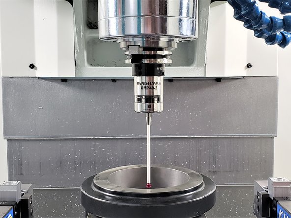
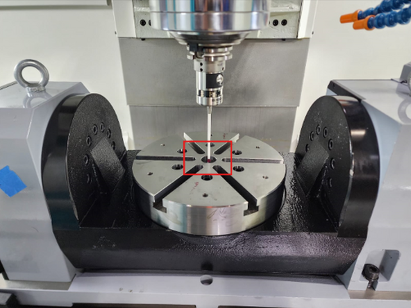
Set up the probe at the center of the platter, just below the top surface, as shown in the screenshot for X & Y axis center offset measurement.
-
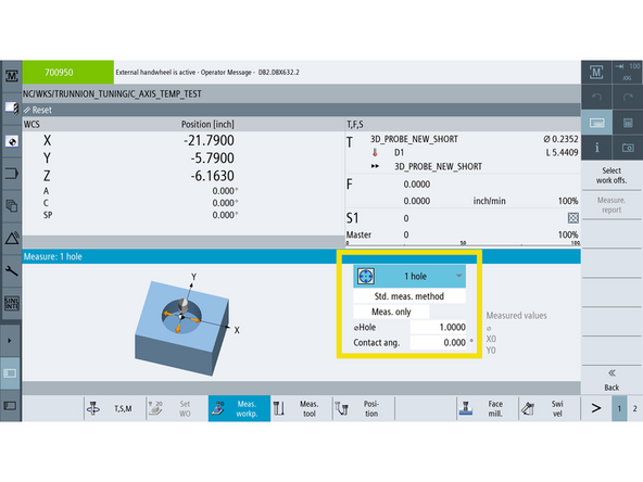
Navigate to [Machine] → [Jog] on MCP → [Meas. Workp] → [Measure 1 Hole].
-
Set the hole diameter to 1.0 inch.
-
Press [Cycle Start], and the probe will measure the hole and find the center.
-
In [Trak Options], input the X and Y values from the probe measurement into the Trunnion Position section.
-
-
-
Set up the probe on top of the platter, as shown in the screenshot, for Z-axis offset measurement.
-
Navigate to [Machine] → [Jog] on MCP → [Meas. Workp] → Measure Z-Axis Edge (Square with one arrow).
-
Press [Cycle Start], and the probe will measure the Z-axis height of the platter.
-
Apply the platter offset correction using the formula: Measured Z Offset + (-0.2)
-
For Example: (-20.44) + (-0.2) = (-20.64)
-
0.2 accounts for the platter offset relative to the A-axis center of rotation.
-
In [Trak Options], input the updated Z-axis measurement with the applied platter offset correction.
-
-
-
Navigate to [Setup] → [Page 2] → [Licenses] → [All Options].
-
Confirm the following licenses are active before running the 5-Axis Loader program:
-
2-axis test license: 6FC5800-0BA00-0Yx0
-
5-axis machining package: 6FC5800-0BS43-0YX0
-
Kinematics measuring license: 6FC5800-0BP18-0Yx0
-
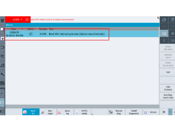
If the licenses are not enabled, you will get Error 61099: Block 994 Internal Cycle Error when trying to run 5AXISKINCHAIN in Step 7.
-
-
-
-
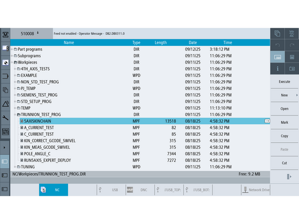
Go to [Program Directory] → Work Piece → TRUNNION_TEST_PROG.
-
Run the 5AXISKINCHAIN program from this folder.
-
Press [Cycle Start] to execute the program and set up the kinematic chain.
-
Press [Reset PO] to apply the new offsets. Press [OK] to continue through the warnings. The machine will reboot.
-
If Error 12550 appears, navigate to [Setup] → [Machine Data] → [General MD] and confirm the following values are set correctly:
-
N18866 $MN_MM_NUM_KIN_TRAFOS = 1
-
N18880 $MN_MM_MAXNUM_KIN_CHAIN_ELEM = 20
-
-
-
-
Ensure the A-Axis and C-Axis positions are set to 0.
-
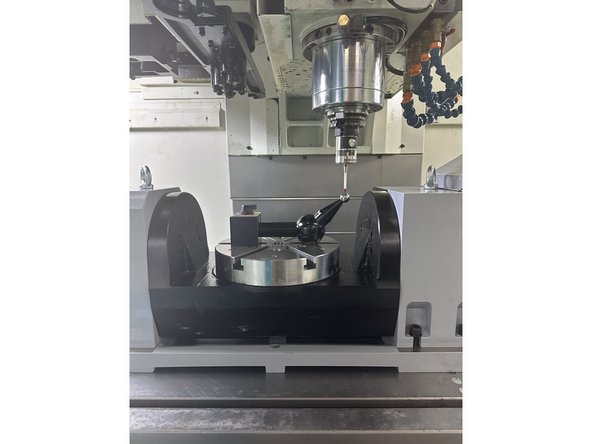
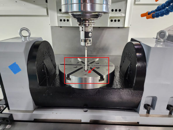
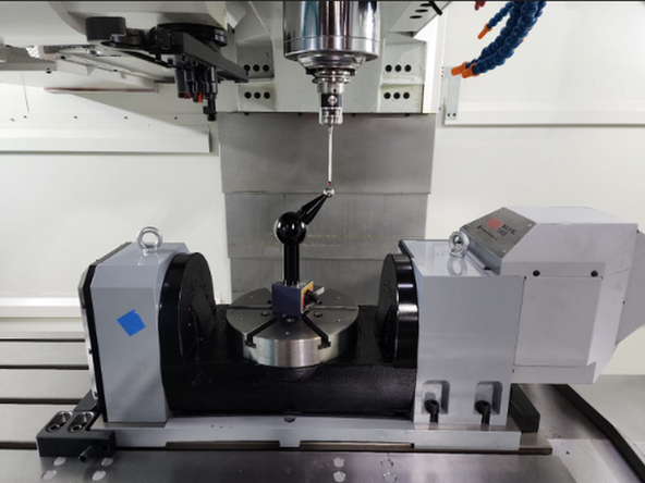
Position the ball of the calibration sphere at the 3 o’clock position (X-positive direction) on the C-axis (rotary) as shown in the picture.
-
Place the probe approximately at the center of the ball and about ¼” above it.
-
Set the work offset from the [T, S, M] screen for all axes at this point.
-
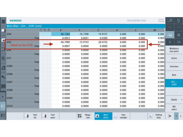
Navigate to the [Work Offset (WO)] menu and select G55 as the active work offset.
-
Use the [Set Actual Position] function to store the measured position as X = 0, Y = 0, Z = 0.
-
If the probe tip fails to follow the calibration sphere correctly when the A-axis rotates, repeat Steps 4, 5, and 6. Pay close attention to Step 5 (Z-axis offset calculation).
-
-
-
Open [Program Manager] and navigate to [Trunnion Directory].
-
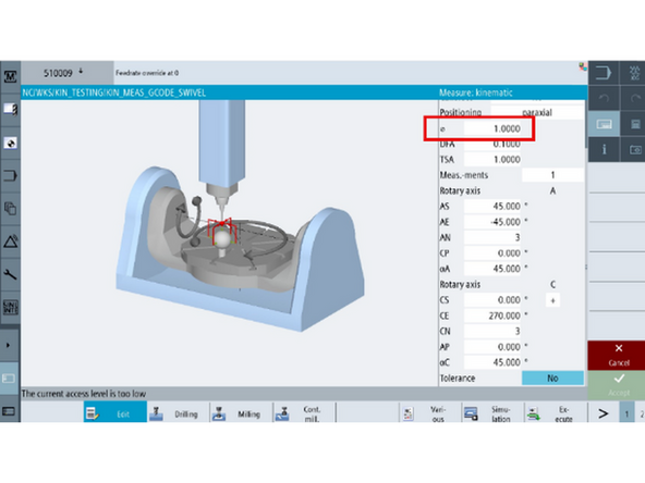
Select KIN_MEAS_GCODE_SWIVEL from the work directory.
-
In Cycle9960, set Kinematic to Meas. Only.
-
Using a micrometer, verify the calibration sphere diameter is 1.000 inch.
-
Enter 1.000 into the program field for sphere size.
-
Run the program to execute the kinematic measurement cycle. (Must be in Manufacture Level Access)
-
If you run into Error 61426: Block N699065; Some of the active offsets does not equal zero-error code: %
-
Go to [Offsets] → [Work Offsets] and make sure no offset is applied to G55.
-
-
-
VMCsi 7 & 10 use 50mm Probe Stylus for Trunnion Calibration.
-
Position the calibration sphere with a magnetic base vertically at the 3 o’clock position (X-positive direction).
-
Repeat Step 8 and 9 to run the kinematic measuring cycle again.
-
-
-
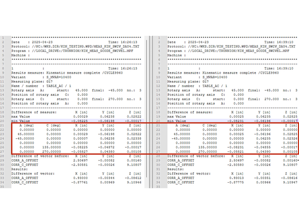
Every time KIN_MEAS_GCODE_SWIVEL is executed, a new entry is added to the MEAS_KIN_SWIV_DAY4 file. New entries added to the bottom.
-
This can be found in [Program Manager] → [Workpieces] → [Kin Testing] → [MEAS_KIN_SWIV_DAY4]
-
Compare measured results from both horizontal and vertical calibration sphere placements.
-
The image shows a side-by-side comparison of the horizontal and vertical measurement results.
-
Check the "Difference of measure" section in both results. The values, highlighted in the red box, should be within 0.008” (8 thou, not eight-tenths) of each other to confirm proper alignment and eliminate skew.
-
If any value exceeds 0.008”, the alignment is incorrect. Restart the calibration and verify your setup.
-
-
-
Only continue on Step 12 if skew from Step 14 was within 0.008”
-
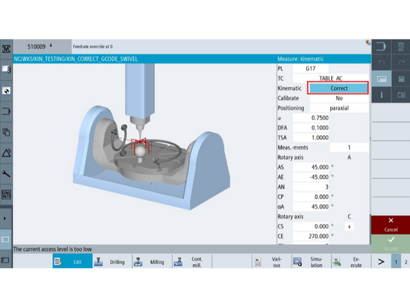
Select the "KIN_CORRECT_GCODE_SWIVEL" program from the work directory.
-
In Cycle9960, set Kinematic to "Correct" if it is currently set to "Meas. Only".
-
Using a micrometer, measure the diameter (in inches) of the calibration sphere to confirm its size. The sphere should be 1 inch.
-
Run the program as performed in Step 14 with the calibration sphere vertically standing up.
-
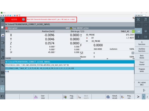
After the program completes, message (62315) will pop up.
-
Press [NC Start], all kinematic data will be overwritten.
-
-
-
VMCsi 7 & 10 use 50mm Probe Stylus for Trunnion Calibration.
-
Position the calibration sphere with a magnetic base vertically at the 3 o’clock position (X-positive direction).
-
Repeat Step 9 to run the kinematic measuring cycle again.
-
Measuring Cycle, not Correction Cycle.
-
-
-
Navigate to [Program Manager] → [Workpieces] → [Kin Testing] → [MEAS_KIN_SWIV_DAY4]
-
Compare results from both vertical measurement and vertical correction.
-
Check the "Difference of vector before" section in both results. The values, highlighted in the red box, should be within 0.008” of each other to confirm proper alignment and eliminate skew.
-
If any value exceeds 0.008”, the alignment is incorrect. Restart the calibration and verify your setup.
-
-
-
Press [E-Stop].
-
Go to [Setup] → [2nd Page] → [Setup Archive] → [All data of this machine] → [Ok]
-
(1) Make sure all boxes are checked.
-
(2) Select the [Archive name] data field. Name the file: Backup_NPDHS-YYYY-MM-DD_TRUNNION_ENABLED. Press [OK].
-
Note: YYYY-MM-DD is the current date (e.g., June 26, 2023, is written as 2023-06-26 in the archive name).
-
The default storage path should be [Archives/Manufacturer]. If the storage path is anything other than the default, change it by pressing [Change storage path] → [Archive/Manufacturer] → [OK].
-
Please send copy of updated archive to TRAKMT Support.
-
![If at any time a new X, Y, or Z offset is changed in the [TrakMT Options] screen, or if X, Y, or Z axis is re-referenced, this entire calibration procedure must be completed again.](https://d3t0tbmlie281e.cloudfront.net/igi/trakmtsupport/RZwH4oRMRjGZqnMr.medium)
![Navigate to [Machine] → [Jog] on MCP → [Meas. Workp] → [Measure 1 Hole].](https://d3t0tbmlie281e.cloudfront.net/igi/trakmtsupport/G6MFD4RMAwCxoQUU.medium)
![Navigate to [Machine] → [Jog] on MCP → [Meas. Workp] → Measure Z-Axis Edge (Square with one arrow).](https://d3t0tbmlie281e.cloudfront.net/igi/trakmtsupport/DDbAGoRM43GZqnMr.medium)
![Navigate to [Setup] → [Page 2] → [Licenses] → [All Options].](https://d3t0tbmlie281e.cloudfront.net/igi/trakmtsupport/AiDFcwRMqkClDdvK.medium)

![Open [Program Manager] and navigate to [Trunnion Directory].](https://d3t0tbmlie281e.cloudfront.net/igi/trakmtsupport/FyaTEPRLpdK2W6xu.medium)

![Navigate to [Program Manager] → [Workpieces] → [Kin Testing] → [MEAS_KIN_SWIV_DAY4]](https://d3t0tbmlie281e.cloudfront.net/igi/trakmtsupport/lG5r4NRMmLCJvXnB.medium)
![Press [E-Stop].](https://d3t0tbmlie281e.cloudfront.net/igi/trakmtsupport/HHBSJgRLbZCxoQUU.medium)
![Go to [Setup] → [2nd Page] → [Setup Archive] → [All data of this machine] → [Ok]](https://d3t0tbmlie281e.cloudfront.net/igi/trakmtsupport/J3wJJgRLrBK2W6xu.medium)
Cancel: I did not complete this guide.
One other person completed this guide.