-
-
TMC has the option to have X, Y and Z handwheels included with your mill. The handwheels are mounted on the rail in front of the machine.
-
To Install:
-
The TMC's option key must be programmed to include this option. Under STATUS, the user can also turn the EHW’s on and off. See Step 14 for location.
-
Electronic Hand Wheels are a proprietary option on a wide range of TRAK Mills, which provide a high level of precise control over the movement of X, Y and Z axis while providing a high level of protection for the operator. EHW's allow for control of each individual axis while also incorporating the TRAKing feature.
-
Our ProtoTRAK software provides control of these handwheels at various speeds. There is a fast course mode to allow rapid movement on a mill when not close to a work area or other objects. We also provide precise fine control over the hand wheels when needed for slow accurate movement while zeroing out an axis as well as other tasks.
-
A valuable reference is provided, see the 31200 pdf file at the end of this guide.
-
Safety First - While working on our equipment: Turn power off and remove power source from the mill.
-
-
-
SAFETY ITEM – Turn Off Power to Mill. Disconnect Power Cable from Mill.
-
Remove "WARNING Do not operate before shutting door." sign below front door . Four holes are to be sealed from the rear with silicone.
-
Drill holes for the X & Y Axis along the front panel as shown. Dimensions are measured from the left front edge of the TMC.
-
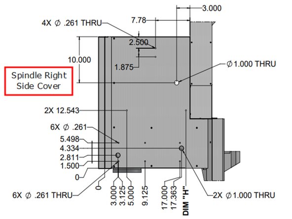
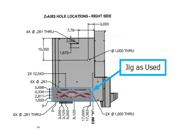
Drill holes for the side panel using the drawing. Dimensions are measured from the upper edge of the cabinet.
-
-
-
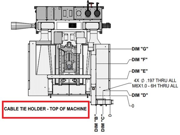
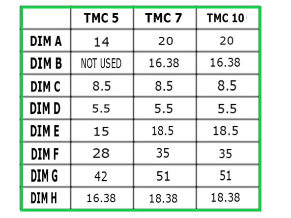
“B” and “C” dimensions measure away from the right side of the mill while the other dimension in the table measure away from the front of the mill.
-
Drill Holes on top of TMC at locations “D” Thru “G” (Holes are hard to see on the drawing).
-
See table for the hole locations and the table for the dimension from “0” of the front of the mill.
-
After drilling, these holes are tapped as M6X1.0 – 6H; drilled and tapped all the way thru the top surface.
-
-
-
Remove right side spindle cover from mill. Drill holes for the Z axis EHW on the right side of the spindle cover using drawing for location and the table for DIM ”H”.
-
DIM "H":
-
TMC 5 16.38"
-
TMC 7 18.38"
-
TMC 10 18.38"
-
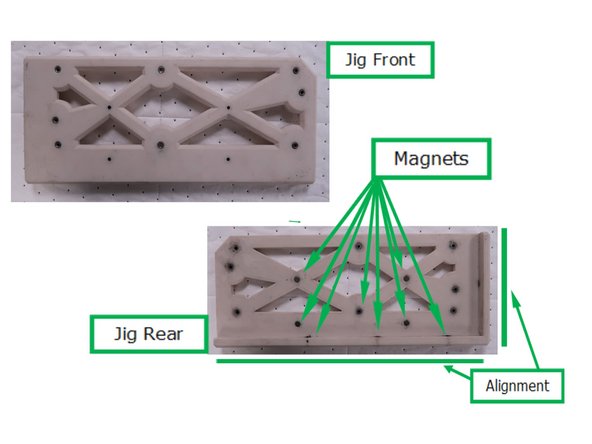
Part of the kit supplied includes a jig that makes it easier to drill the holes along the bottom of the right side cover. It stays aligned with magnets during drilling. The jig creates pilot holes for 2 x 1.0" holes that need to be enlarged using a knockout punch or step-drill.
-
Jig alignment edge for Z Axis right side cover.
-
Jig where used, magnets hold it in position.
-
-
-
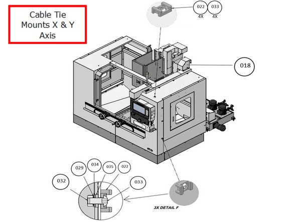
Add cable tie mounts to the side and top of the TMCs as shown. Use part number 22 Cable Tie Mount.
-
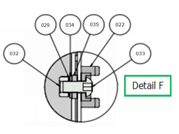
Detail F: Assembly Enlargement
-
Part numbers in circles refer to the parts list available as a pdf file at the end of the procedure and in the last step in this procedure.
-
Four cable tie mounts are held directly into threaded holes in the top (from Step 3). The side locations require more parts. Specific hardware and order of assembly are shown in the Detail.
-
-
-
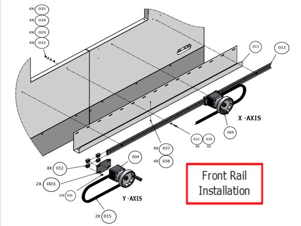
Illustrated are the hardware requirements to attach the front rail, cable channel and EHWs to the front of the mill. Refer to the Parts list in the rear of the document for the hardware detail needed in the steps.
-
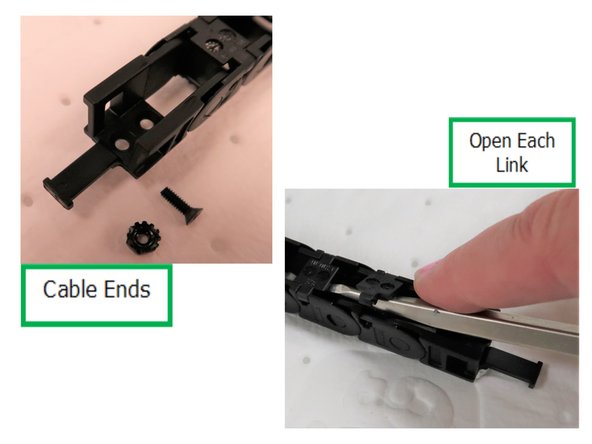
X & Y EHWs need to have their electronic cable installed into the cable carrier chain by prying each link as shown. The ends of both cable carriers have different genders as needed. Attach cable ends to each cable carrier by prying. Attach EHW to double rail.
-
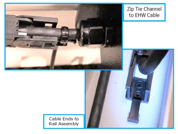
Attach cable carrier with electronic cable to EHW on rail. At the EHW end of the cable carrier a Zip Tie is used on the cable end tab to attach to the cable. The rail end of the cable carrier is attached to the rail with two screws and locking nuts.
-
-
-
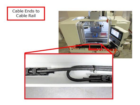
The X Axis cable at the cable rail end is bent over the Y axis cable and then tie banded together.
-
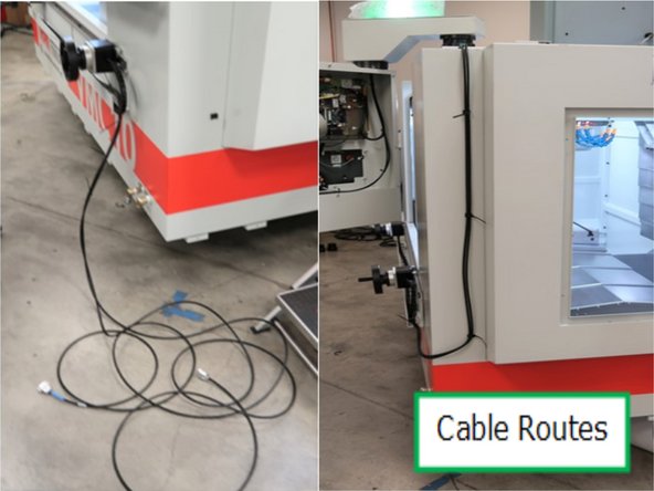
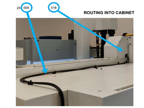
Route X & Y Axis cables from the front rail up along the side. Use Zip Ties to hold wires in place and trim the tails.
-
Use Zip Ties across the top to hold wires in place and trim the tails. The EHW option kit for TMCs 7 or 10 will provide a replacement panel for part number 18 shown with an opening to route the wires.
-
The TMC5 EHW option requires the installer to modify the current piece (018) to allow entrance of the wires into the cabinet.
-
Future plan: Part #18 will come with a knockout that can be removed with pliers easily.
-
-
-
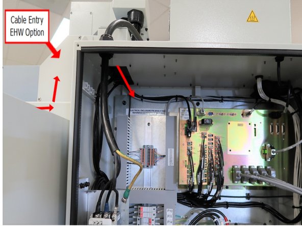
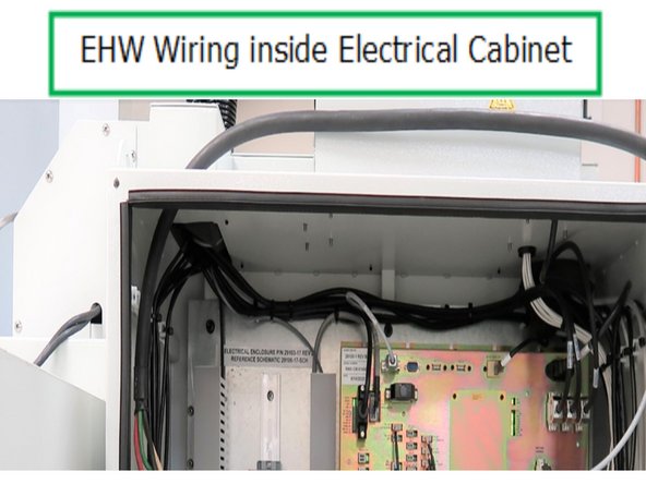
Route wires thru the cabinet from the top thru the removed Cable Entry Sheet Metal panel (Part # 18) and into the electrical cabinet as shown.
-
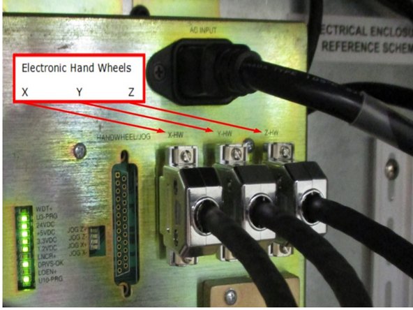
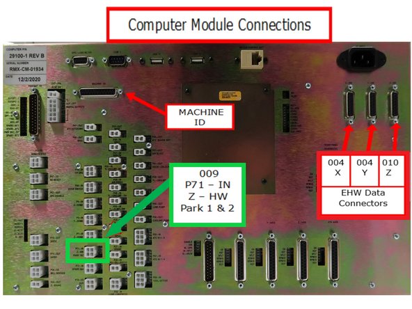
Also provided is the wiring location for X & Y Axis cables on the computer module.
-
Installed wires are Zip Tied to cable tie mounts along top of electrical cabinet just above the computer module.
-
-
-
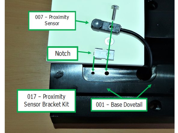
Install the Proximity Sensors pair (Part Number 7) into the Base Rail (Part Number1) using the holes matching the location of the sensor wires on the spindle side cover as shown.
-
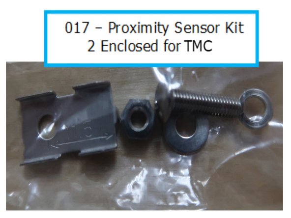
Proximity Sensor kit order of assembly. Lock washer and nut are not used from kit. M3 screw goes into sensor, flat washer between sensor and bracket, and then attach assembly into base dovetail. Notch on bracket slides into hole on dovetail.
-
Manufacturing has recorded errors indicating a malfunction of either one of the sensors. This has been corrected by putting a washer behind the sensor bracket and reassembling the problem sensor. This makes the sensor closer to the moving rail.
-
Part number 017 is supplied in a bag and contains an assortment of 5 parts as shown. Two kits are supplied for the front and rear sensors.
-
-
-
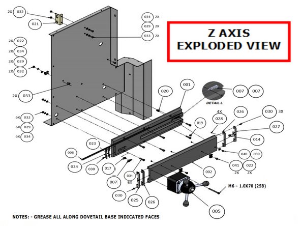
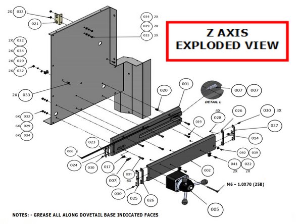
Attach Dovetail Base to Spindle Side Cover using the required hardware listed on the Parts List. Attach the Z EHW to the Slider Dovetail (Part Number 2) with the specified hardware. The Z Axis cable remains loose and will be attached directly to the spindle side later.
-
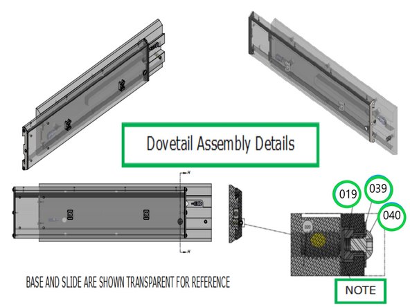
Plunger is installed from back of dovetail base BEFORE mounting dovetail base to spindle side cover.
-
Insert Plunger part number 20 and place flush to top of base, assemble parts 19, 39, and 40 but do not tighten item 40. Adjust slide and base so that all items are aligned, then tighten part 40.
-
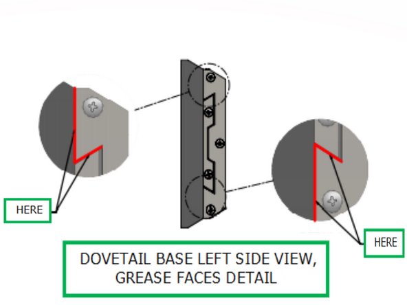
Lube the Dovetail base all along surfaces in red on the Gibs using any water-resistant bearing grease that conforms to ISO VG 68 to 100 standard. Feed the Proximity Sensor wires thru the Spindle Right side cover. Assemble the remaining parts including wipers, wiper stop, etc., as referenced.
-
Refer to McMaster #3382A16 plunger drive in order to adjust spring plunger part 20 from front side of dovetail base. (Plunger drive not included with installation kit).
-
-
-
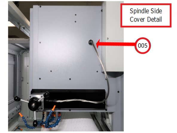
Attach Z EHW cable (Part Number 5) to the cable tie holders on the Slider Dovetail with Zip Ties. Install Liquid Tight connector on Z Handwheel cable thru the Spindle side cover.
-
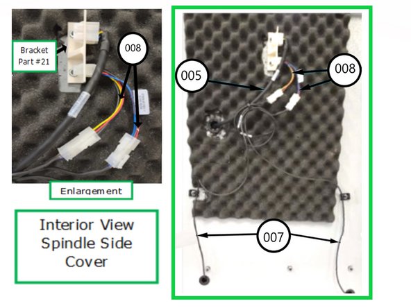
Install Bracket Part # 021 to side panel. Some of the foam will need to be cut and removed. Install Z axis handwheel cable and slider proximity switch cable and pig tail to bracket as shown.
-
Manufacturing has seen errors reported on the screen indicating a malfunction of either one of the sensors. This has been corrected by putting a washer behind the sensor bracket and reassemble the problem sensor. This makes the sensor closer to the moving rail.
-
Reattach right ride Spindle cover on the Spindle.
-
-
-
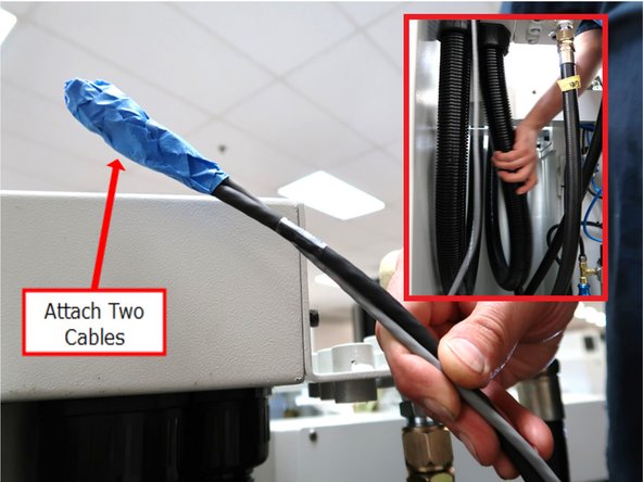
Tape together Z EHW Park Cable (Part # 009) and Z Handwheel Extension Cable to be pulled through the conduit. Inset photo shows assembler adjusting flex conduit while feeding cable. Cable can get caught on ribs inside.
-
An Electricians Fish Tape can be used with the wires to make pulling the wires through the conduit easier.
-
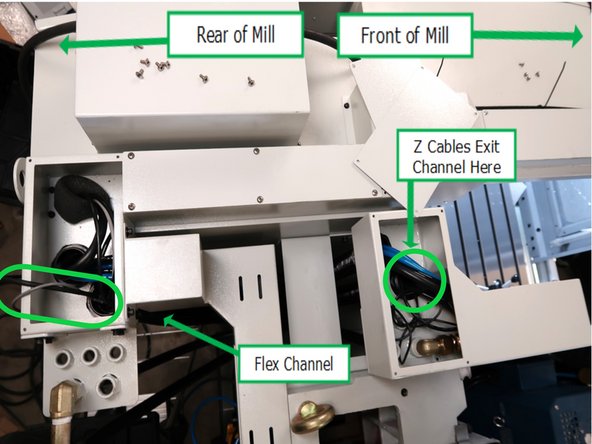
This photo has a green highlight on the left side of the photo around the area where the cables are being fed thru the flex channel. The right side of the photo shows where the taped cables will emerge.
-
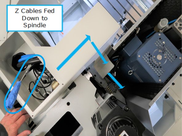
Next the taped cables are thru the channel shown on the left of the photo and will be routed thru the case down to the spindle opening as shown.
-
-
-
Connect Z Cables fed down thru case tunnel to the Z Axis bracket on the Spindle side cover as shown. Connectors are unique and will only connect correctly.
-
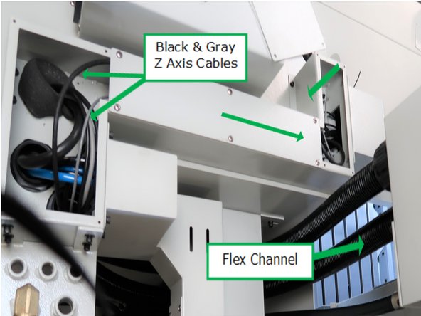
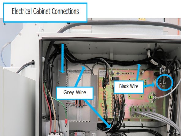
At the rear of the mill, the other end of the black and gray cables are routed thru the tunnel down to the Electric Cabinet for connection to the Computer Module.
-
Wires routed into Electrical Cabinet. Attached black wire to Z Axis Connection. Connect grey wire to connection labeled P-71-IN-Z-HW Park 1&2 on the computer module.
-
See the next step to see the specific cable locations on the computer module.
-
Replace access covers and screws, attach Zip Ties.
-
-
-
Computer Module diagram showing the locations of the EHWs going to the computer. Numbers refer to Parts List.
-
Part number 009 the proximity sensor wires for the Z EHW plug into the input labeled P71.
-
Almost done!
Finish Line


