Parts
No parts specified.
-
-
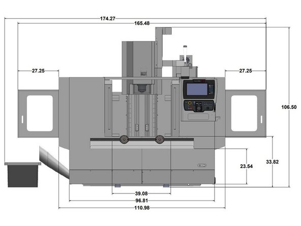
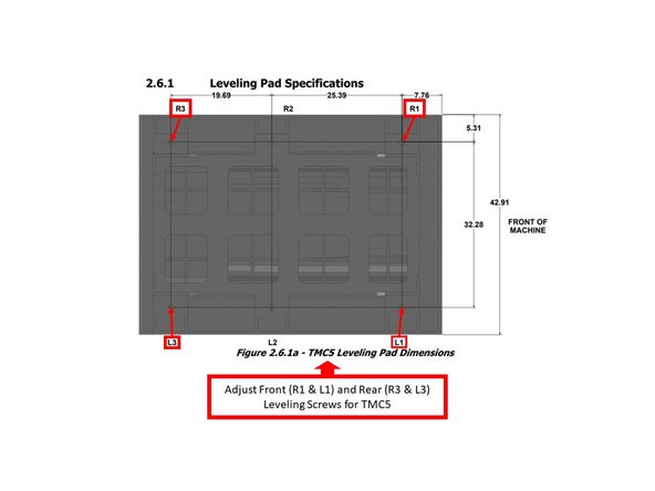
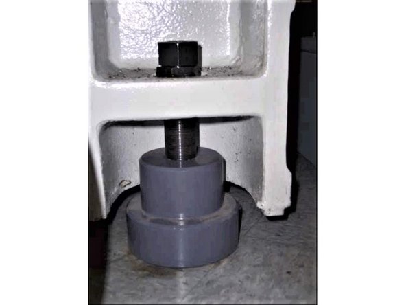
The following images show the external dimensions and locations of the feet for leveling for the TRAK TMC5.
-
-
-
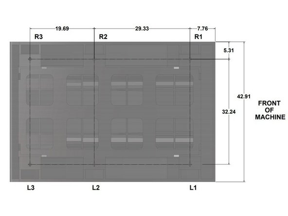
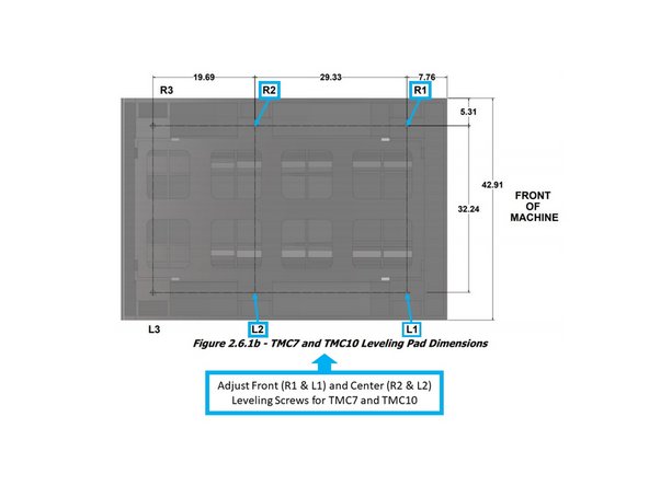
The following images show the external dimensions and locations of the feet for leveling for the TRAK TMC7.
-
Please note that the TRAK TMC7 and TMC10 have similar base casting dimensions.
-
-
-
The following images show the external dimensions and locations of the feet for leveling for the TRAK TMC10.
-
Please note that the TRAK TMC7 and TMC10 have similar base casting dimensions.
-
-
-
Leveling the TMC in the field consists of leveling the machine and then adjusting the level, if necessary, to make sure that the tram of the spindle is perpendicular to the table.
-
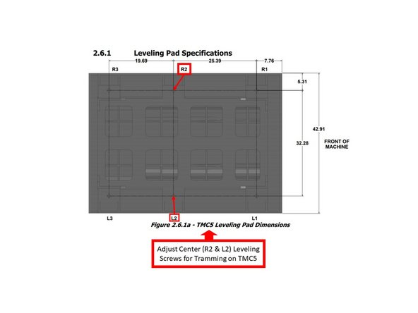
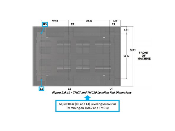
Please refer to the previous Steps 1 - 3 for the details to be used to level your specific TRAK machine. The locations of L1, L2, L3, R1, R2, & R3 are shown in the photos.
-
Clean the table thoroughly, and place one or two precision Spirit levels or electronic levels at the center of the table (as shown on the image).
-
If using two levels, make sure that each level is measuring correctly. To check, place the level in one direction and note the reading. Next, flip the level 180º, and see if the reading is the same. If not, have the level recalibrated.
-
With the precision levels placed on the worktable as shown, level the TMC to be within spec of 0.0005”/10".
-
-
-
On the TMC5, adjust leveling screws R1, R3, L1 and L3 in order to meet the required spec.
-
Adjusting screws R2 and L2 should be left loose or just snug with the leveling pads, and have no pressure at this time. A 36 mm wrench is required to adjust the leveling bolts.
-
On the TMC7 and TMC10, if the spec of 0.0005”/10" is not achieved, adjust leveling screws R1, R2, L1 and L2.
-
Adjusting screws R3 and L3 should be left loose with the leveling pads, and have no pressure at this time. A 36 mm wrench is required to adjust the leveling bolts.
-
If the machine must be anchored to the floor, follow the general instruction for installing machine tools when anchoring. When the machine is correctly leveled, lock the adjusting screws in place with their hex nuts.
-
If the machine must be installed on vibration mounts/pads (rubber, commercially available leveling and vibration mounts, etc.), follow the instructions delivered with the mounts/pads, and ensure that the requirements for the load of the machine and the maximum weight of the workpiece (~10,000 lb.) are satisfied.
-
-
-
Mount a .0001" dial indicator to the spindle, and ensure that the dial indicator can sweep a 12" span with a 6" radius across the table.
-
Check the tram on both the X and Y Axes, and ensure that the Total Indicated Runout (TIR) for both axes does not exceed +/- 0.0008"/12".
-
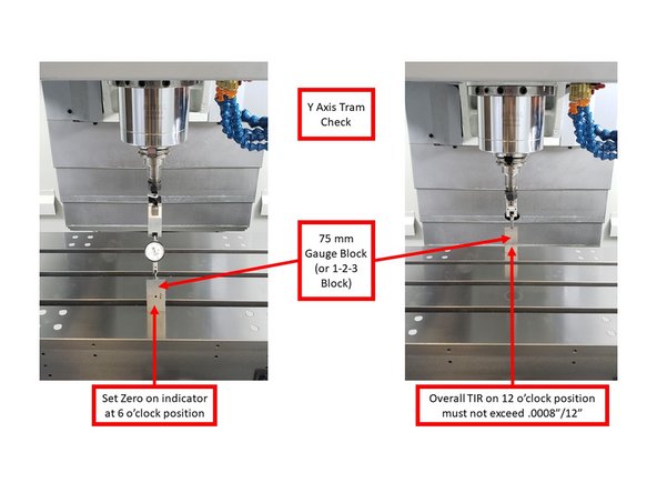
Check the tram on the Y Axis through the following steps:
-
As shown on the image, set zero on the dial indicator at the 6 o'clock position. Use a 75 mm gauge block (or a 1-2-3 Block) to ensure accuracy over the surface of the table.
-
Turn the dial indicator on the spindle to the 12 o'clock position (as shown on the image). Check if the TIR on this position does not exceed .0008" over 12". If needed, use an inspection mirror to check the values on the dial indicator while it faces the back wall of the machine.
-
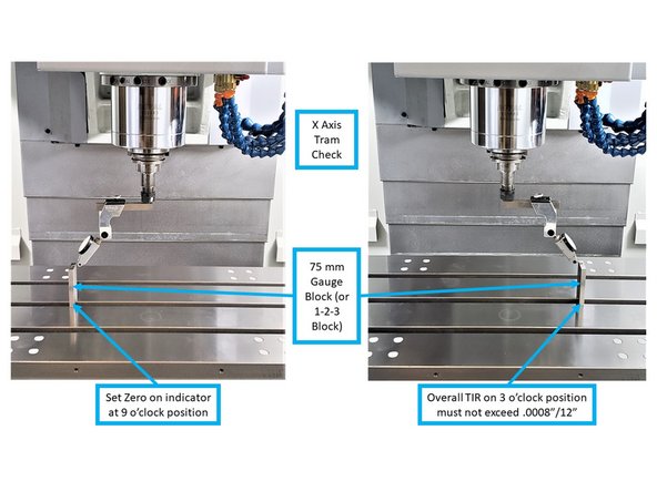
Check the tram on the X Axis through the following steps:
-
As shown on the image, set zero on the dial indicator at the 9 o'clock position. Use a 75 mm gauge block (or a 1-2-3 Block) to ensure accuracy over the surface of the table.
-
Turn the dial indicator on the spindle to the 3 o'clock position (as shown on the image). Check if the TIR on this position does not exceed .0008" over 12".
-
-
-
If the tram measurement exceeds .0008" TIR on the TMC5, adjust the R2 and L2 leveling screws to adjust the tram within specification. This will help adjust any errors you have in the X and Y Axes for the tram. By adjusting these screws, you can slightly affect the column and bring in the tram.
-
If the tram measurement exceeds .0008" TIR on the TMC7 and TMC10, adjust the R3 and L3 leveling screws to adjust the tram within specification. This will help adjust any errors you have in the X and Y Axes for the tram. By adjusting these screws, you can slightly affect the column and bring in the tram.
-
Recheck the tram for both the X and Y Axes on the machine to be within .0008"/12". This process may need to be repeated if the floor surface is less than ideal.
-
Once complete, lock all leveling screws in place with the lock nuts.
-


