Introduction
The TRAK TMC12 and TMC14 are larger than TRAK's standard machining centers, and they are also more sensitive to leveling screw adjustments. The additional mass of the machine affects the process, and can make the machine sag or flex unpredictably if the process is not done in a controlled manner.
Tools
Parts
No parts specified.
-
-
Leveling the TMC12 and/or TMC14 in the field consists of initially leveling the machine and then adjusting the leveling screws to make sure that the tram of the spindle is perpendicular to the table.
-
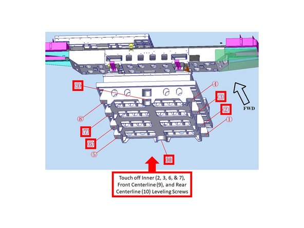
This image is a model of the TRAK TMC12/TMC14 base casting and table, viewed from the front.
-
We will be using these number designations to identify and callout each leveling screw.
-
-
-
The Inner four (4) leveling screws (labeled as 2, 3, 6, & 7), and the Front (9) and Rear (10) centerline leveling screws should be left loose with the leveling pads, and should have no pressure at this time.
-
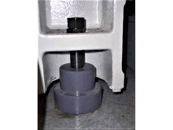
An extended 36 mm wrench is required to adjust the leveling bolts.
-
Check the front to back level of the machine to be within 0.0005"/10" by placing the digital and/or bubble level at the center of the table, vertical on the Y Axis, as shown on the image.
-
Adjust the outside four (4) leveling screws (labeled on the image as 1, 4, 5, and 8) in order to achieve the above spec, and also adjust these leveling screws in pairs when leveling the machine.
-
Next, check the left to right level of the machine to be within 0.0005"/10" by placing the digital and/or bubble level at the center of the table, horizontal on the X Axis, as shown on the image.
-
Again, adjust the 1, 4, 5, and 8 leveling screws in pairs in order to achieve the above spec.
-
-
-
Mount a .0001" dial indicator to the spindle nose, and ensure that the dial indicator can sweep a 12" span (6" radius) across the table.
-
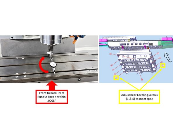
Check the front to back tram of the machine by manually sweeping the dial indicator from front to back (half-circle on the Y Axis) of the table, as shown on the image. The front to back tram spec should be within .0008".
-
If the above spec is not achieved, adjust the rear leveling screws (1 and 5) to push or pull on the column, relative to the table.
-
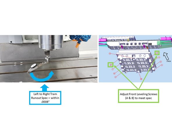
Check the left to right tram of the machine by manually sweeping the dial indicator from left to right (half-circle on the X Axis) of the table, as shown on the image. The left to right tram spec should be within .0008".
-
If the above spec is not achieved, adjust the front leveling screws (4 and 8) to lift and lower the table, relative to the Z-column casting.
-
Several of the machines will actually have a twist rather than a simple planar error. This twist can be compensated by either lowering the high end or lifting the low end of the twist. Most machines have had a high spot that required being lowered.
-
The larger mass of the machine allows you to lower the high corner, and it will sag to straighten the casting.
-
-
-
Recheck both Front to Back and Left to Right Tram (Step 3 above) to be within .0008".
-
This process may need to be repeated if the floor surface is less than ideal.
-
-
-
Once the above tramming processes are up to spec, touch off the Inner four (2, 3, 6, & 7), and the Front (9) and Rear (10) Centerline Leveling Screws.
-
They should be firm and snug, with no changes to the pressure against the ground.
-
-
-
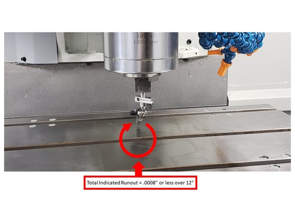
Complete a final tram check to make sure that values are within spec:
-
Using the dial indicator, sweep the table with a 12" span (6" radius).
-
The tram should be .0008" or less over 12".
-
Once complete, lock all leveling screws in place with the lock nuts.
-