Introduction
These procedures cover the basic hardware kit installation on step 1. Additional steps help the Factory or FST with the complete 4th Axis installation on a TMC. Here are the steps along with the Dozuki Guide References:
Please make sure to load software version 2.3.0 or higher prior to 4th axis installation.
1. Install on TMC - TMC 4 Axis 31538: Install Hardware "Ready Kit" & Test -- Steps 1 - 7 are the hardware "Ready Kit"; Steps 8 onward start testing the hardware install when the 4th Axis unit is available.
2. Y, Z Offset, Base Tool - TMC 4 Axis 31538: Set Y & Z Offsets & Base Tool Offset
3. Backlash - TMC 4 Axis 31538: Set Backlash
Reference Document:
A pdf version of drawing 31538 is attached to the end of this document. It covers the location of all items, how the parts are assembled, and the part numbers used to build the drive.
-
-
Minor Changes need to be made to the TMC sheet metal in order to operate the 4th Axis. The cable harness mounting bracket on the right side interior ceiling needs to be punched out.
-
Three covers on the right side of the top of the mill need to be removed to allow the addition of wires. The wires coming from the 4th Axis will be routed through two openings at opposite sides of the electrical cabinet.
-
#1 has the mounting bracket, all the wires route through #2 and the power extension wire is routed through the channel above the electric cabinet #3.
-
Document 31538 is attached at the end of this guide. It is a very complete document showing the parts and how they fit together including a part list with the part numbers and their description.
-
-
-
Delta Servo drive needs to be added to the left of the filter. Photo shows the servo drive installed with the inset showing the area before adding the drive.
-
Use (3) M5-0.8x12 25B screws, (3) 24009-4 Belleville lock washers and (3) M5 70B flat washers, in that order, are inserted into the mounting holes for the servo drive.
-
-
-
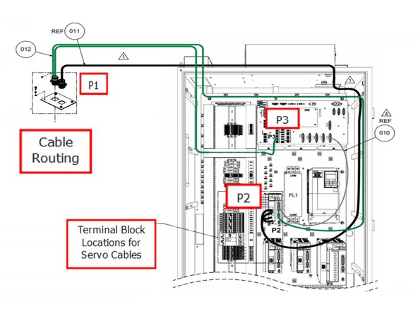
Routing diagram for the needed cables to operate the 4th Axis.
-
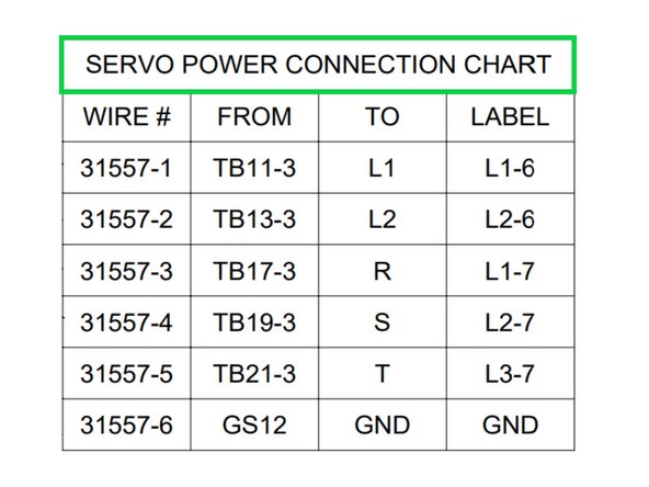
Specific wire locations from the servo drive to the terminal block.
-
-
-
Cable Routing diagram, refer to drawing 31538 included at the end of this guide for further information.
-
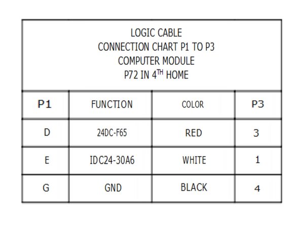
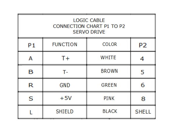
Use charts to connect wires
-
Cable #12 part # 26844-35 contains two cables, the length and connections make it clear where they are attached, to either P2 or P3.
-
Cable #11 part # 26840-32 is routed to P2.
-
Cable #10 part # 22443-8 is routed from P2 to the computer module P3.
-
Replace covers as needed when all the wires have been added.
-
-
-
Important Notice!
-
For field installations, the servo drive is preprogrammed at our factory, so no need to complete the next two steps. TRAK factory installs will need to complete the next two steps to program the drive.
-
Prior to programming servo drives. Ensure ESTOP is activated. Power will be "ON" for the mill. After programming the drives, you will be able to HOME the machine and RUN the axis.
-
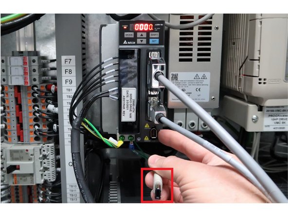
Use a DELTA USB-cable to program one axis at a time. Connect the USB-cable to CN3 of the servo drive. Connect the other end to the laptop.
-
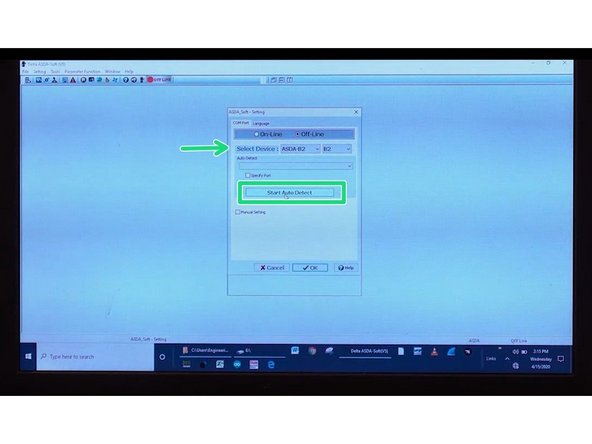
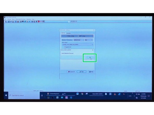
On the laptop open the DELTA ASDA_Soft. Click start auto detect, verify ASDA-B2 is selected (Use the drop down menu to do so if not already selected). Click OK on the pop up window.
-
-
-
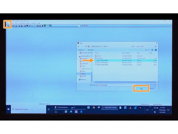
Depending on the machine you are working on, select the correct program for the 4th Axis. The revisions on these programs may vary as updates occur.
-
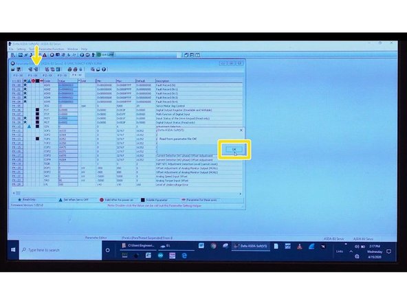
Click FILE, then OPEN, and select the 4th Axis TMC 4th Axis REV ?.par (For "?" - check in machine assembly for latest rev version). File click OPEN, and click OK. Notice a window will prompt a message, "Read from parameter file OK?" Click OK.
-
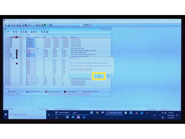
At the top, find and click the WRITE PARAMETERS icon. A window will prompt you a message. Click YES. It will override the parameters, click OK.
-
Cycle Power to have the new parameters take effect.
-
-
-
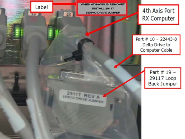
In order to add the 4th Axis to a TMC with no 4th Axis, a jumper must be removed, and replaced with Delta Drive cable.
-
Remove jumper from 4th Axis port on the computer, and place it in a bag. That bag is tie wrapped to the computer end of cable #10 part # 22443-8. Connect cable #10 from the 4th Axis Delta drive to 4th Axis port on computer.
-
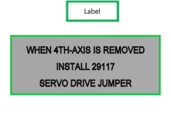
Attach part #22 "4th Axis removed" label directly to computer module. as shown in previous step.
-
This completes the hardware installation, 4th Axis ready kit. The next step will test the 4th Axis if it is available. Otherwise, the mill is ready for the 4th Axis when available.
-
-
-
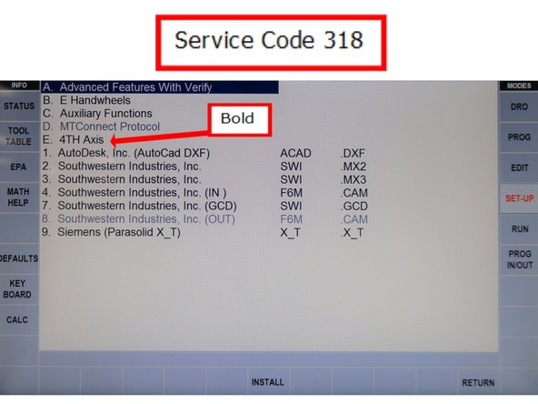
Make sure that the machine’s Option Key has been programmed for this option by checking it with Service Code 318.
-
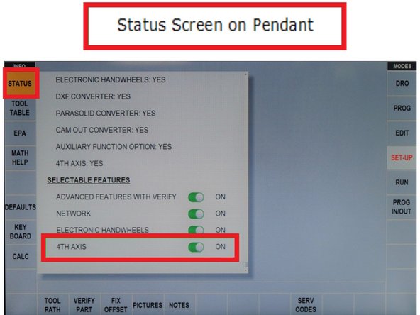
Confirm if the 4th Axis is enabled for your machine by accessing the STATUS screen on the programming control, scrolling down to SELECTABLE FEATURES, and making sure that 4TH AXIS is ON.
-
The ProtoTRAK software will prompt a reboot of the control when the 4th Axis Option is switched from OFF to ON. If the control was turned off with the 4th Axis being in the ON position, then it should boot up with the option being ON as well.
-
For factory inspectors, record results on your inspection sheet.
-
-
-
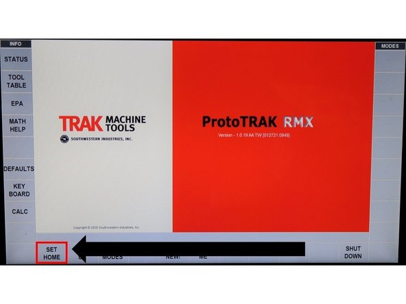
To run the Home Routine Test, choose SET HOME on the control. Make sure that the Servos are on by checking if the Power Reset LED light is on.
-
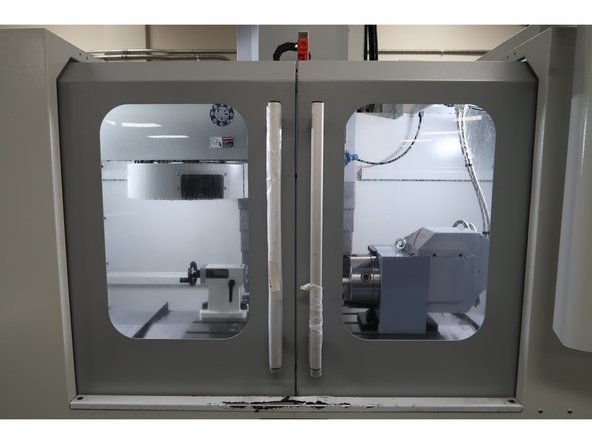
Make sure that the machine doors are closed.
-
Once the SET HOME screen appears, press GO as instructed.
-
If 4th Axis homes properly, the red LED should turn on; the home indicator block will not directly be underneath the sensor.
-
If the 4th Axis homes correctly, then the Home Routine Test is successful. Fix any appropriate errors that may arise.
-
For factory inspectors, record results on your inspection sheet.
-
-
-
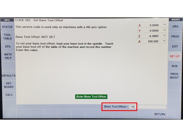
In order to setup the machine to allow the 4th Axis to run, the Base Tool Offset must be entered via Service Code 502.
-
Press SET-UP, enter Service Code 502, and press ABS SET. Follow the prompt that appears on screen, and press OK. Enter "-19" under Base Tool Offset. Click ABS SET.
-
For factory inspectors, record results on your inspection sheet.
-
Once the above is complete, press RETURN to allow you to go into the next Service Code.
-
-
-
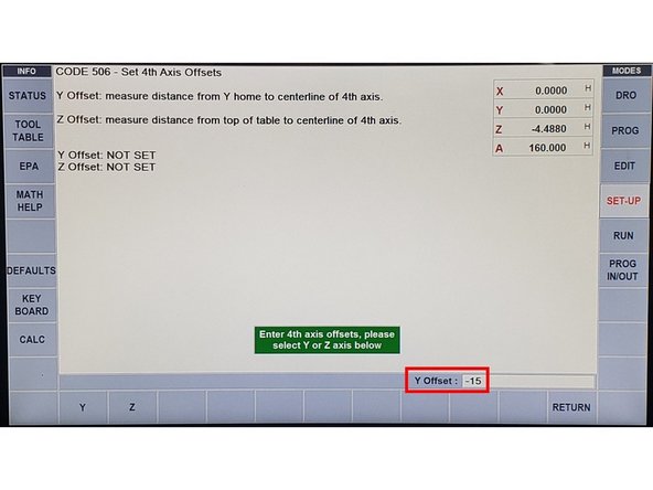
In order to set up the Y Offset and Z Offset, it must be entered via Service Code 506.
-
Go into Service Code 506. Press Y, and enter the following value = -15. Click ABS SET.
-
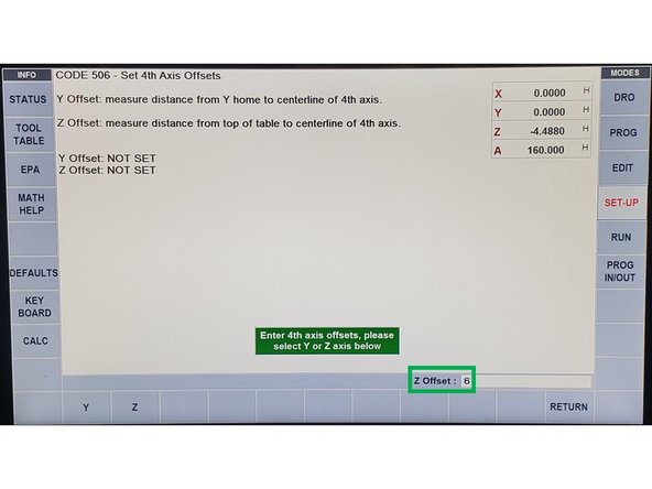
Press Z, and enter the following value = 6. Click ABS SET.
-
For factory inspectors, record results on your inspection sheet.
-
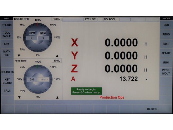
Once the above steps had been completed, press RETURN twice. You should see a gray display.
-
-
-
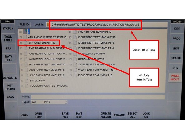
The Run-in Test allows users to verify that the 4th Axis can run a test program without any errors. Before running the program, make sure that the chuck is empty.
-
Access the Run-in Test by pressing PROG IN/OUT. Open the file named 4TH AXIS RUN IN.PT10. Click OPEN.
-
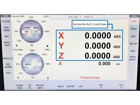
Go to DRO Mode, press Go To, and then press Y and Z Offset. Turn on the EHW, and jog the Y-Axis until the value is 0. Repeat this process for the Z-Axis as well. Once completed, hit RETURN twice back to DRO Mode.
-
In addition, make sure that the X-Axis is centered.
-
Zero out all the axes by pressing the desired axis, and press ABS SET.
-
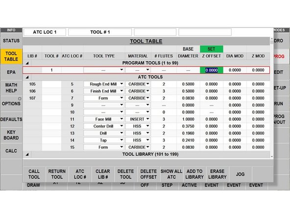
Next, press TOOL TABLE on the left side of the screen. Press NOT SET (orange), then INC SET to set it to the proper Z height (which turns green). Input “0” under Z Offset, and press INC SET (which turns green). This step must be completed; otherwise, the program will not run. To exit, press TOOL TABLE.
-
Once the coordinates had been set to zero, click RUN, START, GO, YES (you do not have to load any tools), and then GO. The 4th Axis Run-in Test should begin. Verify if the program runs without any error. When program is done, press YES, and then GO. The screen will display Run over.
-
Program will run the 4th Axis clockwise and then counterclockwise. For factory inspectors, record results on your inspection sheet.
-
-
-
FST Staff:
-
If the 4th Axis is to be installed by FST in the field, then leave it enabled. If the 4th Axis is to be removed for later use, turn off the 4th Axis in the status screen, turn mill off, remove servo drive cable, and replace with jumper. Cable should be tie banded to the jumper. Reboot the mill, and verify that the 4th Axis is disabled.
-
Trak Factory Inspector:
-
The 4th Axis should be returned to the packaging for shipping when done. The 4th Axis option needs to be disabled on the TMC for shipping, turn off the axis in the status screen, turn mill off, remove servo drive cable, and replace with jumper. Cable should be tie banded to the jumper. Reboot the mill, and verify that the 4th Axis is disabled.
-