
Introduction
These procedures help with a 4th Axis installation on a TMC. Here are the steps along with the Dozuki Guide References:
Please make sure to load software version 2.3.0 or higher prior to 4th axis installation.
1. Install Kit - TMC 4 Axis 31538: Install Hardware "Ready Kit" & Test
2. Y, Z Offset, Base Tool - TMC 4 Axis 31538: Set Y & Z Offsets & Base Tool
3. Backlash - TMC 4 Axis 31538: Set Backlash
-
-
Verify the TMC has no obstructions on the table. Make sure 4th axis is enabled in STATUS screen, and make sure machine has been homed.
-
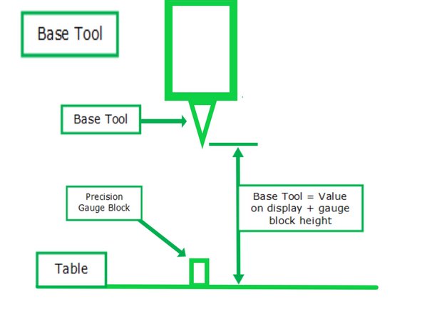
Place the Base Tool in the spindle. Make sure that you are using the same base tool for measuring tool offsets.
-
Enable Service Code 502 by clicking SET-UP > SERV CODES > Input “502” on the Service Code # field > ABS SET > Yes.
-
The Service Code 502 – Set Base Tool Offset screen will appear. On this screen, a table with X, Y, Z, and A values is provided; these values reflect the distance of the base tool’s current location away from the machine’s home position.
-
Place a precision gauge block below the spindle. Record the precise height of the gauge block that you are using for reference (For example, your gauge block has a height of 2”). Slowly jog down the Z-Axis until the tip of the base tool touches the top of the precision gauge block.
-
Use the fine .001” resolution of the EHW to slowly jog and more accurately pinpoint the height.
-
Referencing the table within Service Code 502, note the Z-Axis value of the base tool’s current location on top of the precision gauge block. Add the precision gauge block’s height to this value, and the total will be the base tool offset value.
-
Enter this number within the Z Axis field, hit ABS SET.
-
-
-
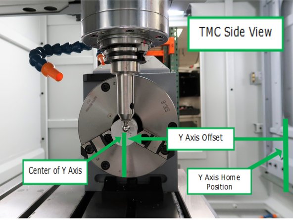
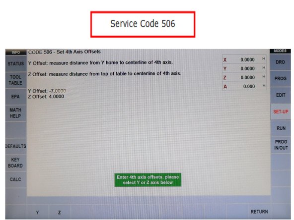
Service code 506 allows the operator to locate the centerline of the 4th Axis from home position. When the offsets are defined in the pendant, the mill will be able to safely work on parts using the 4th Axis.
-
Home the mill. Run Service Code 506. Set the X value to 0. Code 506 will provide fields to input the Y and Z Offsets.
-
Mount a round part in the 4th axis. Choke up on the part to cut it as close to the chuck as possible when you cut a flat at 0° on the part. Rotate the part 180° and cut another flat on the part. Make sure to cut the flat at the same Z depth for both cuts. Take a micrometer and measure the distance between the flats and note this value.
-
Face either flat spot perpendicular with the front of the mill. Take a dial indicator and set the indicator and DRO of the control to zero when touching. Align the 4th Axis along the X axis so the edge finder will hit the cut part in the 4th axis. Move the y axis rearward until the edge finder just touches the flat side of the part.
-
When the edge finder just touches the part, take the Y Home value on the screen, add half the thickness of the edge finder plus half the thickness of the part. That’s the value that should be entered for Y Offset.
-
-
-
For the Z offset, there are a couple ways we recommend measuring this offset.
-
Gage Pin Method:
-
Mount a ground gage pin in the chuck of the 4th axis. Make sure the pin is running true before measuring the height. Adjust the pin in the jaws as necessary to minimize runout. You may also want to make sure the chuck is running true before clamping down on the pin.
-
Take a dial indicator and set the indicator and DRO of the control to zero when touching the top of the table.
-
Now take the indicator and move the Z axis up and zero the indicator out on top of the pin. Find the highest point of the pin. Take this DRO Z value and subtract ½ of the diameter of your ground pin. This is your Z offset.
-
Press Z at the bottom of the screen and enter the value.
-
-
-
For the Z offset, there are a couple ways we recommend measuring this offset.
-
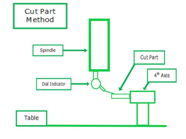
Cutting a Part Method:
-
Mount a round part in the 4th axis. Choke up on the part to cut it as close to the chuck as possible when you cut a flat at 0° on the part. Rotate the part 180° and cut another flat on the part. Make sure to cut the flat at the same Z depth for both cuts. Take a micrometer and measure the distance between the flats and note this value.
-
Take a dial indicator and set the indicator and DRO of the control to zero when touching the top of the table. Now take the indicator and move the Z axis up and zero the indicator out on top of the flat on your part. Take this DRO Z value and subtract ½ of the width of the part you measured. This is your Z offset.
-
Press Z at the bottom of the screen and enter the value.
-


Cancel: I did not complete this guide.
One other person completed this guide.