Tools
Parts
No parts specified.
-
-
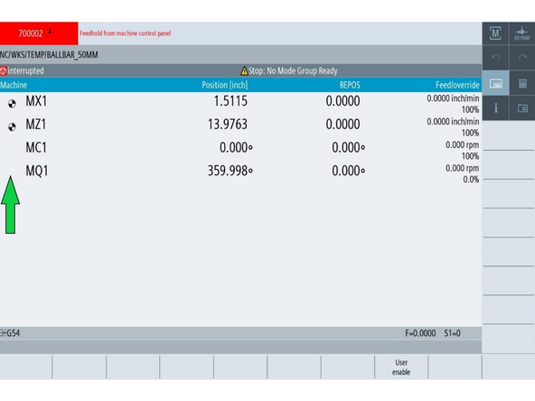
The green arrow in the image points to an axis without a reference set (no icon shown).
-
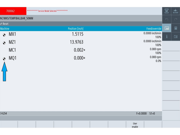
The blue arrow points to an axis with the reference icon — a black-and-white circle.
-
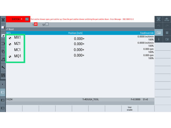
Press [JOG] and [REF POINT] on the MCP.
-
On the [Machine] screen, look for the reference icon beside each axis (e.g., MQ1, MX1, MZ1).
-
This black-and-white symbol confirms the axis has a valid absolute encoder reference. If the icon is missing, the encoder is not referenced and must be set.
-
All servo axes must display this icon before the machine is fully operational.
-
The chuck (MC1) does not display a reference icon because it is not a servo axis and does not require referencing.
-
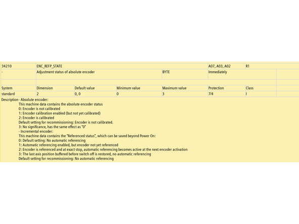
The encoder state is internally tracked using MD34210, which will be reviewed in the next step.
-
-
-
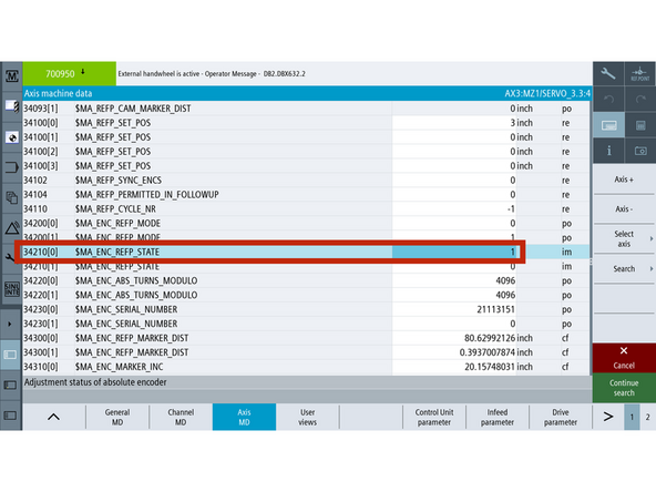
Before an axis can be referenced, the control must be told the encoder’s current state. This is tracked using MD34210, which determines whether the encoder is unreferenced, ready to calibrate, or already calibrated.
-
MD34210 set as 0: Encoder Not Calibrated. The encoder has no reference to the physical position. Use this to clear or reset the reference.
-
MD34210 set as 1: Calibration Enabled. Encoder is ready to establish a new reference. This is the manual setup state.
-
MD34210 set as 2: Encoder Calibrated. The encoder position is successfully established, and the machine recognizes the axis position.
-
-
-
The Q-axis represents the degree of rotation of the turret.
-
Move the turret to Position 1
-
Go to [Machine]→ [TSM] → [Select Tool] → Select Tool 1 and press [Cycle Start].
-
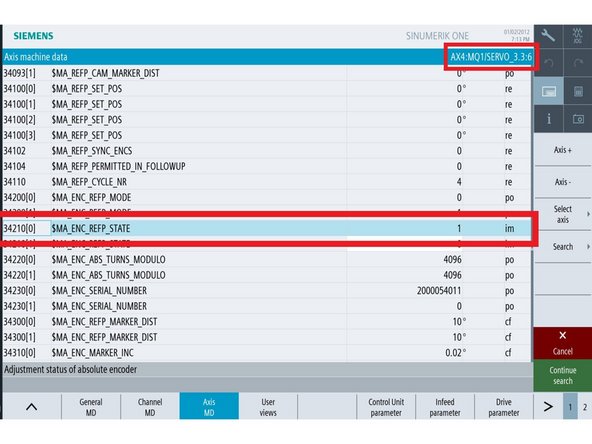
Go to [Setup] → [Mach. Data] → [Axis MD] → [Select Axis] → [MQ1/SERVO] → [OK].
-
Press the [Search] button and type 34210.
-
Set MD34210[0] = 1
-
Press [Reset PO] to reboot the machine.
-
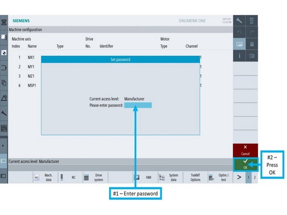
Log back into Manufacturer Mode
-
-
-
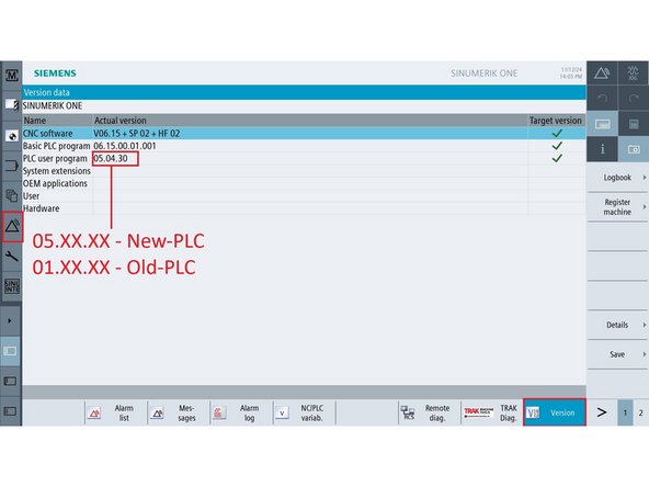
This determines which DB address to use in Step 6.
-
All LTY and LTY-S machines are on New-PLC
-
On the control, go to [Diagnostics] → [Version].
-
Locate the PLC User Program version.
-
If version starts with 05.XX.XX, it is New-PLC.
-
If version starts with 01.XX.XX, it is Old-PLC.
-
-
-
Go to [Diagnostic] → [NC/PLC Variable]
-
In an empty row under Variable, enter the proper bit:
-
Old-PLC → DB34.DBX4.7
-
New-PLC → DB37.DBX4.7
-
Set the Format to [B].
-
On the MCP, press both [JOG] and [REF POINT].
-
Press [Change], enter 1, then press [Input] → [OK]. The bit will toggle back to 0 automatically.
-
Confirm the Q-axis shows the reference icon.
-
-
-
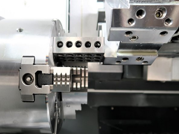
Mount a turret toolholder with a square, machined face in Position 1.
-
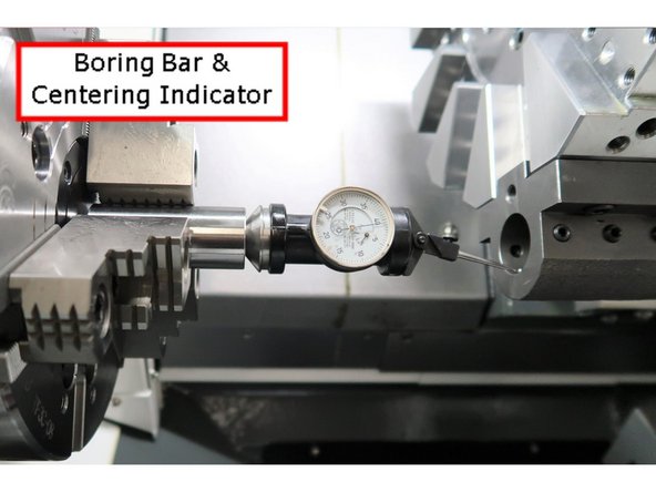
For TC820si: Use a boring bar block or standard OD (Outside Diameter) turning tool holder with a flat machined face (e.g., facing or roughing tool block).
-
For TC820LTY and TC820LTY-S: Use a radial live tool holder (facing the spindle) with a square machined face.
-
Insert a centering indicator into the spindle
-
Jog X and Z to bring the indicator into contact with the toolholder face.
-
Go to [Machine], press [Act. values MCS] to display Machine Coordinates.
-
Sweep the X-axis back and forth; adjust Z until runout is < 0.001" across +X and −X.
-
This Z-axis position defines the turret’s X0 mechanical centerline.
-
-
-
Go to [Setup] → [Mach. Data] → [Axis MD] → [Select Axis] → [MX1/SERVO] → [OK].
-
Press the [Search] button and enter 34210, then press [OK].
-
On the MCP, turn on [JOG] and [REF. POINT].
-
Set MD34210[0] = 1
-
For TC820 & TC820LTY: Press [+X].
-
For TC820LTY-S: Press the [X] axis button, then press [+].
-
Confirm the X-axis shows the reference icon.
-
-
-
Z0 is established by bringing the turret face into contact with a known-height reference object placed against a defined machine surface.
-
The Z-axis reference value is calculated by subtracting the reference object’s height from the machine position at the moment of contact.
-
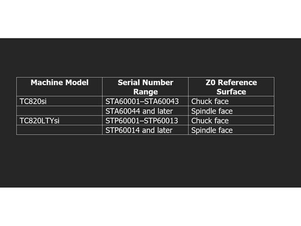
The correct surface to place the reference object depends on the machine model and serial number.
-
TC820si: Serial STA60001–STA60043: Reference from the chuck face.
-
Serial STA60044 and later: Reference from the spindle face.
-
TC820LTYsi Serial STP60001–STP60013: Reference from the chuck face.
-
Serial STP60014 and later: Reference from the spindle face.
-
TC820LTY-Ssi All models reference from the spindle face.
-
-
-
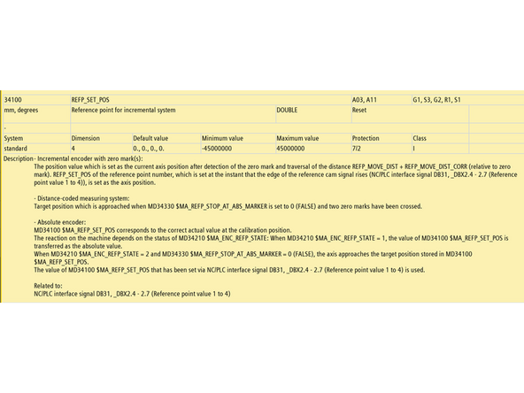
MD34100 tells the control what machine coordinate to assign to the axis during encoder referencing.
-
This value must reflect the height or distance of the physical reference used — such as a 1-2-3 block, 6.000" gauge block, or spindle-to-spindle spacer.
-
Set per axis, MD34100 (Step 11) must be entered before referencing using MD34210 (Step 15) to ensure the encoder aligns with the actual position.
-
-
-
Set MD34100 to match the exact height of the measuring tool or reference stack used when physically referencing the Z1 axis.
-
This value will be assigned as the machine coordinate for Z1 during encoder calibration.
-
TC820 / TC820LTY: Use the block height touched off in Step 12.
-
TC820LTY-S: Use the calculated value from Step 13 & 14: Z1 Reference Value = [Block Height] + A + B
-
Once you have the correct value:
-
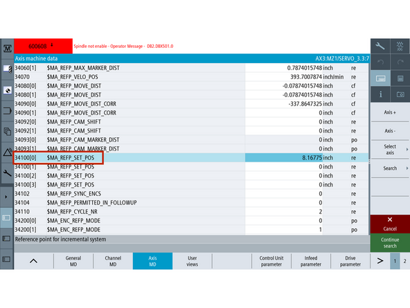
Go to [Setup] → [Mach. Data] → [Axis MD] → [Select Axis] → [MZ1/SERVO].
-
[Search] and enter the value in MD34100.
-
This must be set before referencing the encoder in Step 15.
-
-
-
Remove any tool holder from the turret and clear the spindle face (remove any part or chuck jaws).
-
Place a known-height precision block on the correct surface (see Step 9 for which face to use).
-
Slowly jog the Z-axis until the turret face makes light contact with the block.
-
Ensure there is no visible gap, but do not compress or deflect the block.
-
This contact point is +X.XXX" from actual Z0, where X.XXX = height of your reference block.
-
Go to [Machine], press [Act. values MCS] to switch to machine coordinates.
-
Note the MZ1 machine position while the turret face is in contact with the block — this value will be used to set MD34100 in Step 11.
-
-
-
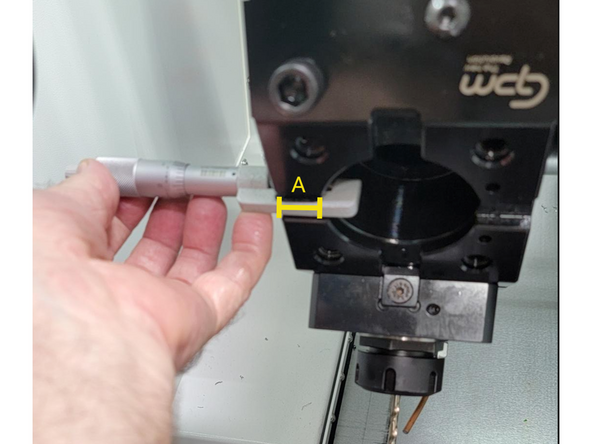
Use turret Position 1 and work directly with the live tool mounting bore
-
Insert a dial indicator into the spindle and align it with the front face of the bore.
-
Jog the X-axis back and forth to verify face squareness.
-
Deflection across the sweep should be less than 0.001".
-
Measure the distance from turret face to tool face — this will be recorded as A.
-
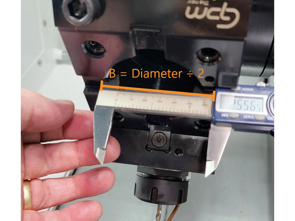
Measure the distance from tool face to tool centerline of the live tool cavity (½ the bore diameter) — this will be recorded as B.
-
These two values (A and B) will be used in the next step to calculate the Z1 reference position.
-
Remove the indicator from the spindle before proceeding.
-
-
-
Place a precision gauge block (6.000" or longer) firmly against the main spindle face.
-
Jog the turret forward until the tool face makes light contact — do not compress the block.
-
Confirm the previously recorded block height, A, and B values from Step 13.
-
Calculate the total: Z1 Reference Value = [Block Height] + A + B.
-
Go to [Machine] → [Actual Values MCS] to display machine coordinates.
-
Record the MZ1 machine coordinate at the moment of contact.
-
This value will be used to set MD34100 in Step 11.
-
-
-
Before continuing, make sure MD34100 has been set correctly in Step 11. This value defines the Z1 position the control will assign during encoder referencing.
-
Go to [Setup] → [Mach. Data] → [Axis MD] → [Select Axis] → [MZ1/SERVO] → [OK].
-
Press the [Search] button and enter 34210, then press [OK].
-
On the MCP, turn on [JOG] and [REF. POINT].
-
Set MD34210[0] = 1
-
For TC820 and TC820LTY: Press [+Z].
-
For TC820LTY-S: Press the [Z] axis button, then press [+].
-
Confirm the Z-axis shows the reference icon.
-
-
-
MD36100 and MD36110 define the allowable travel range for the Z1 axis after referencing. These soft limits must safely enclose the Z1 reference position established in Step 15.
-
Go to [Setup] → [Machine Data] → [Axis MD] → [Select Axis] → [MZ1/SERVO].
-
-
-
Ensure the turret is retracted and out of the way.
-
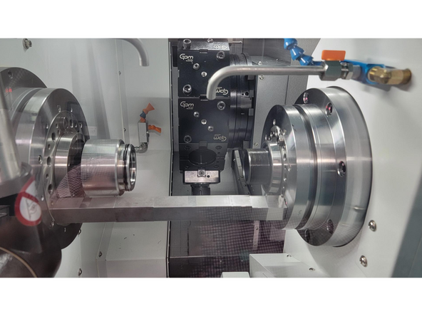
Place a precision gauge block (12.000" or longer) between the main spindle and sub-spindle faces.
-
Jog the sub-spindle forward until light contact is made with the block — do not compress it.
-
Go to [Machine], press [Act. values MCS] to switch to machine coordinates.
-
Note the MZ2 machine position while turret face is in contact with the block.
-
-
-
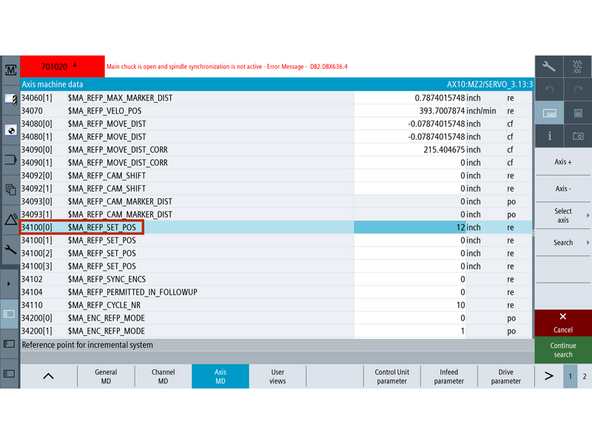
Set MD34100 to match the exact height of the measuring tool or reference stack used when physically referencing the Z2 axis.
-
This value will be assigned as the machine coordinate for Z2 during encoder calibration.
-
TC820LTY-S: Use the MZ2 position noted in the previous step when the sub-spindle face contacted the reference block.
-
On the control, go to [Setup] → [Mach. Data] → [Axis MD] → [Select Axis] → [MZ2/SERVO].
-
[Search] and enter the value in MD34100.
-
-
-
Go to [Setup] → [Mach. Data] → [Axis MD] → [Select Axis] → [MZ2/SERVO] → [OK].
-
Press the [Search] button and enter 34210, then press [OK].
-
Turn on the [JOG], [REF. POINT], and [Z2] buttons on the MCP.
-
Set MD34210[0] = 1
-
Press the [+] button on the MCP.
-
Confirm the Z2-Axis shows the reference icon.
-
-
-
Insert wisdom here
-
-
-
Confirm all required axes display the black/white reference icon: Q, X, Z1, and Z2 (for TC820LTY-S).
-
Archive machine state to preserve encoder references.
-
-
Send new archive to TRAK Tech Support or upload to Config Folder
-
-
-
TC820LTY-Ssi Config Folder
-
![Go to [Diagnostic] → [NC/PLC Variable]](https://d3t0tbmlie281e.cloudfront.net/igi/trakmtsupport/fyOa35RMPwGZqnMr.medium)

![Go to [Setup] → [Mach. Data] → [Axis MD] → [Select Axis] → [MX1/SERVO] → [OK].](https://d3t0tbmlie281e.cloudfront.net/igi/trakmtsupport/PvAl3nRMTOCxoQUU.medium)
![Press the [Search] button and enter 34210, then press [OK].](https://d3t0tbmlie281e.cloudfront.net/igi/trakmtsupport/kKGI3oRMMOGZqnMr.medium)
![Go to [Setup] → [Mach. Data] → [Axis MD] → [Select Axis] → [MZ1/SERVO] → [OK].](https://d3t0tbmlie281e.cloudfront.net/igi/trakmtsupport/IOFp44RMebGZqnMr.medium)
![Go to [Setup] → [Mach. Data] → [Axis MD] → [Select Axis] → [MZ2/SERVO] → [OK].](https://d3t0tbmlie281e.cloudfront.net/igi/trakmtsupport/in233HRMauK2W6xu.medium)