
Introduction
This calibration procedure is essential after a tool crash, software update, or whenever the tool setter is not repeating or reading accurately. It applies to both the TC820si and TC820LTYsi lathe models.
Tool Setter Probe Repeatability:
Across the face: 0.0008" (0.02 mm)
At a fixed point: 0.0004" (0.01 mm)
⚠️ Important Note: Images may only show the X and Z axes. However, ensure that the Y-axis is always at machine zero during this process.
To confirm this, navigate to Act. Values > MCS and check that MY1 = 0.000". Do not move the Y-axis afterward.
⚠️ The clamping mechanism differs slightly between the TC820si and TC820LTYsi, but the alignment procedure is the same.
Tools
Parts
No parts specified.
-
-
Mount a dial indicator with 0.0001" resolution to the tool post or a stable holder.
-
Move the turret so the indicator can contact the face of the tool setter probe.
-
Use the manual jog function to sweep across the X+ side of the probe and note the reading.
-
Sweep across the Z+ side, again noting the reading.
-
Repeat for the X- side and Z- side.
-
Record all four measurements to determine any deviation from axis alignment.
-
The goal is for all four sides to be within 0.0008" (0.02 mm) of each other.
-
If the probe is out of tolerance, proceed to Step 2 to adjust alignment.
-
-
-
Loosen the four mounting screws that hold the tool setter probe in place.
-
Lightly snug the screws so the probe can still be rotated or shifted with slight pressure.
-
Use the dial indicator readings from Step 1 to determine which sides need adjustment.
-
Gently tap or shift the probe until all four sides read within 0.0008" (0.02 mm) of each other.
-
Fully tighten all four mounting screws once alignment is within spec.
-
Recheck all four sides with the dial indicator to confirm the probe did not shift while tightening.
-
If necessary, repeat minor adjustments and recheck until alignment is correct.
-
-
-
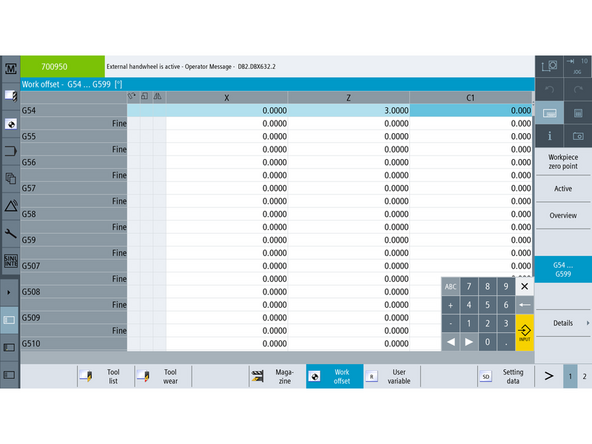
On the control, go to TSM and set the Work Offset to G54.
-
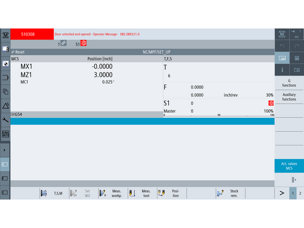
Switch to [Act. Values MCS] on right
-
Jog Axes to X = 0.000" Z = 3.000" (Also, Y = 0.000" if machine has a Y axis)
-
Switch back to WorkOffset, turn off actual values.
-
Press [Set Workoffset]
-
Confirm that X and Z (and Y if applicable) values are now matched to the machine coordinate position.
-
-
-
Insert a ground pin (e.g. 1.000" diameter) into the spindle.
-
Or a known diameter part.
-
Load three tools into any available turret stations:
-
Tool 1: Cutoff Tool
-
Tool 2: Boring Bar
-
Tool 3: Right Turn/Face Tool
-
-
-
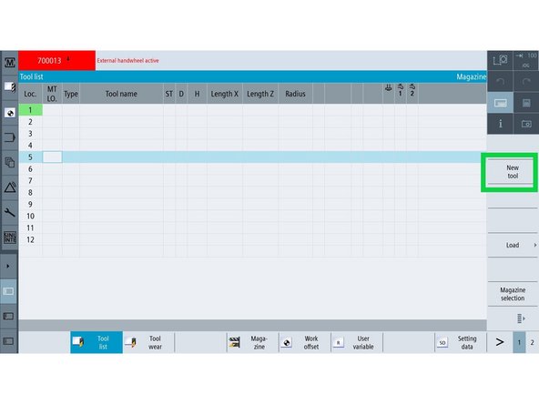
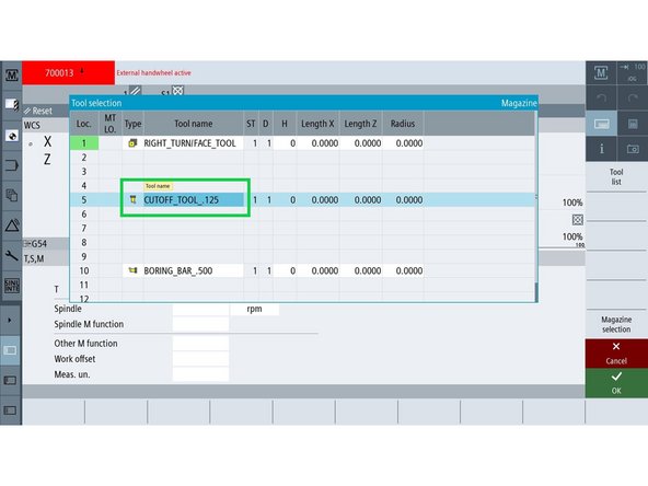
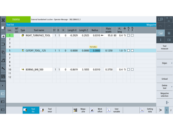
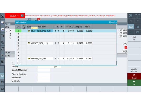
Open the [Tool List] from the left-hand menu.
-
Select the turret position where the Cutoff Tool is installed.
-
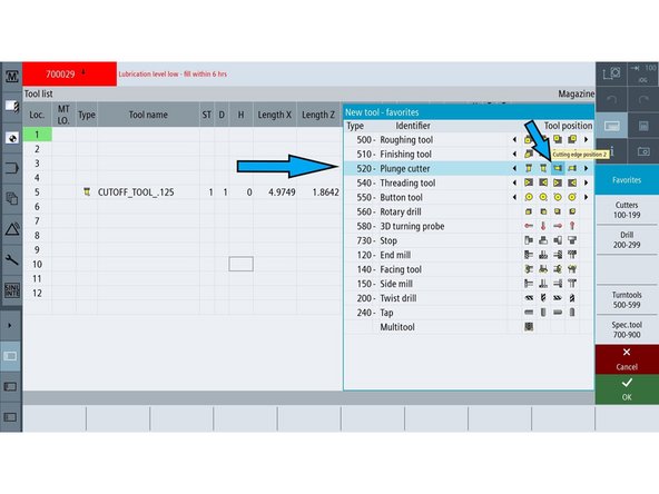
Press [NEW TOOL] on the right-side button panel.
-
Choose PLUNGE CUTTER as the tool type.
-
Click on the 2nd tool tip position (Tip 2).
-
Press [OK] to save the tool setup.
-
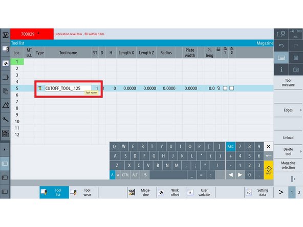
Rename the tool to CUTOFF_TOOL_.125 (or adjust the name based on actual tool width).
-
-
-
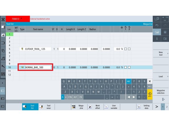
Select the turret position where the Boring Bar is installed.
-
Press [NEW TOOL] on the right-side button panel.
-
Choose PLUNGE CUTTER as the tool type.
-
Click on the 3rd tool tip position (Tip 3).
-
Press [OK] to save the tool setup.
-
Rename the tool to BORING_BAR_.500 (or match your tool diameter if different).
-
-
-
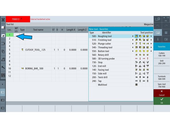
Select the turret position where the Right Turn/Face Tool is installed.
-
Press [NEW TOOL] on the right-side button panel.
-
Choose ROUGHING TOOL as the tool type.
-
Click on the 1st tool tip position (Tip 1).
-
Press [OK] to save the tool setup.
-
Rename the tool to RIGHT_TURN/FACE_TOOL.
-
-
-
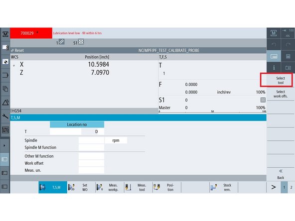
Go back to the TSM screen.
-
Ensure the turret has enough clearance to safely rotate.
-
Press [SELECT TOOL] on the right-side button panel.
-
Highlight CUTOFF_TOOL_.125 (or whatever name was assigned in Step 4).
-
Press [OK] to confirm tool selection.
-
Press [CYCLE START] on the control panel.
-
The turret will rotate and position the selected tool.
-
-
-
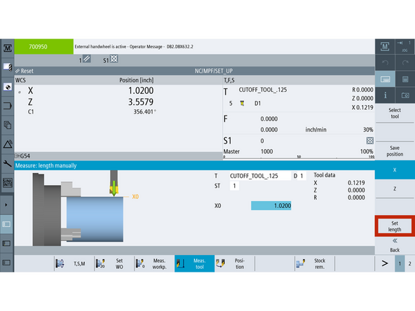
Press [MEASURE TOOL] on the control.
-
Use a .010" feeler gauge between the tool and the positive (front) side of the ground pin in the spindle.
-
Gently pinch the tool and gauge until you feel light resistance.
-
Press [MANUALLY], then press [X].
-
In the X0 input field, enter the measured diameter:
-
Pin Diameter + (Feeler Gauge × 2)
-
Example: 1.000 + (0.010 × 2) = 1.020
-
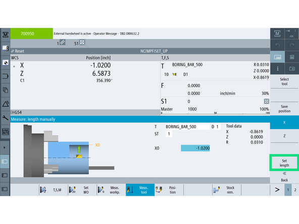
Press [SET LENGTH] to save the X value.
-
-
-
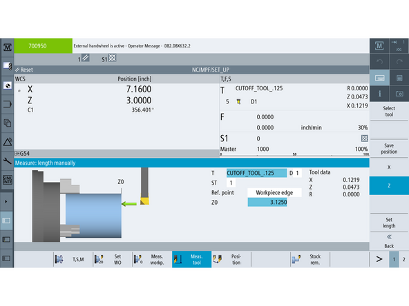
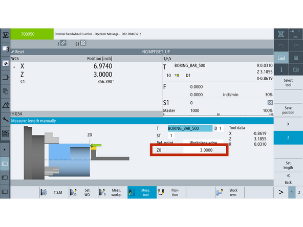
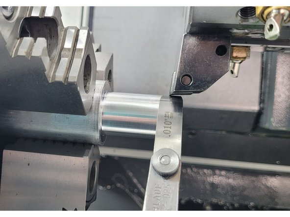
Press [Z] to switch to the Z-axis input.
-
Use a 3" Joe Block between the tip of the cutoff tool and the face of the chuck( Or nose of spindle).
-
In the Z0 input field, enter the total offset:
-
Tool Width + Joe Block
-
Example: 0.125 + 3.0 = 3.125
-
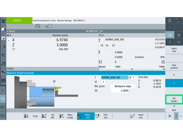
Press [SET LENGTH] to save the Z value.
-
-
-
Move the tool away from the pin to clear space for turret rotation.
-
Ensure there is enough clearance around the turret to avoid collisions.
-
Open the [Tool List].
-
Press [SELECT TOOL].
-
Select BORING_BAR_.500 (or your assigned Boring Bar name).
-
Press [OK] to confirm the tool.
-
Press [CYCLE START] to rotate the turret and bring the tool into position.
-
-
-
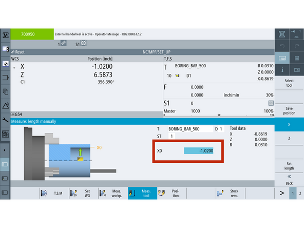
Press [MEASURE TOOL].
-
Use a .010" feeler gauge between the boring bar and the back (negative X) side of the ground pin.
-
Gently pinch until you feel light resistance.
-
Press [MANUALLY], then press [X].
-
In the X0 input field, enter the total value as a negative diameter:
-
Example: -1.020 (1.000" pin + 0.010" gauge × 2)
-
Press [SET LENGTH] to save the X value.
-
-
-
Press [Z] to switch to the Z-axis input.
-
Use a 3" Joe Block between the tip of the boring bar and front of the chuck (Or spindle face)
-
Gently pinch until you feel light resistance.
-
In the Z0 input field, enter the gauge thickness only:
-
Example: 3.0"
-
Press [SET LENGTH] to save the Z value.
-
-
-
Move the tool away from the ground pin to clear the area.
-
Pull the release pin at the base of the probe arm and swing the probe into position.
-
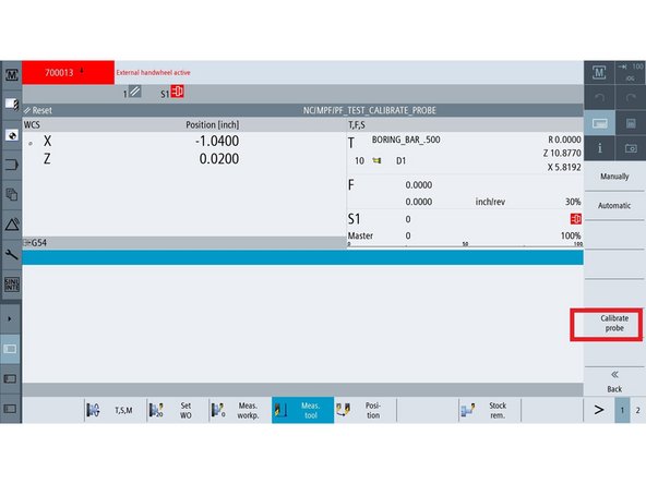
Press [BACK] on the control screen.
-
Press [CALIBRATE PROBE].
-
Press [Z] to begin Z+ calibration.
-
Jog the tool so the tip is approximately ¼" from the right side of the probe button.
-
Confirm the probe is set to move in the correct direction using the on-screen arrows or dropdown.
-
Press [CYCLE START]. The tool will move forward, trigger the probe, then back away — Z+ is now calibrated.
-
-
-
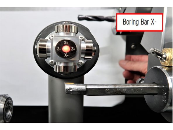
Press [X] to begin X- calibration.
-
Jog the tool so the tip is approximately ¼" from the bottom side of the probe button.
-
Confirm the probe will move in the correct direction using the on-screen arrows or dropdown.
-
Press [CYCLE START]. The tool will move forward, trigger the probe, then back away — X- is now calibrated.
-
-
-
Move the tool away from the probe to ensure clearance.
-
Go to TSM and press [TOOL LIST] from the right VSK. Select the CUTOFF_TOOL_.125 (or your assigned cutoff tool).
-
Press [OK], then press [CYCLE START] to rotate the turret.
-
Press [MEASURE TOOL] on the control.
-
Press [CALIBRATE PROBE].
-
Press [X] to begin X+ calibration.
-
Jog the tool so the tip is approximately ¼" from the top side of the probe button.
-
Press [CYCLE START]. The tool will move forward, trigger the probe, then back away — X+ is now calibrated.
-
-
-
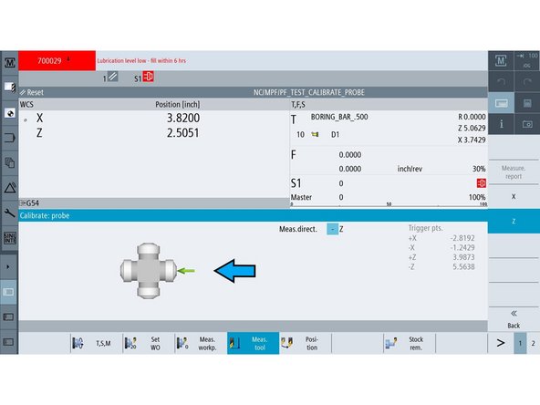
Press [Z] to begin Z- calibration.
-
Jog the tool so the tip is approximately ¼" from the left side of the probe button.
-
Confirm the probe direction is correct using the on-screen arrows or dropdown.
-
Press [CYCLE START]. The tool will move forward, trigger the probe, then back away — Z- is now calibrated.
-
-
-
Press [BACK] to exit manual mode.
-
Press [AUTOMATIC] to enter automatic calibration mode.
-
Press [Z] to begin. Jog the tool tip to about ¼" from the left side of the probe button.
-
Press [CYCLE START]. The tool will touch the probe and move away. ➜ The Z value will not change — This confirms the tool offset.
-
Press [X] next. Jog the tool tip to about ¼" from the top side of the probe button.
-
Press [CYCLE START]. The tool will touch the probe and move away. ➜ The X value will not change — This confirms the tool offset.
-
-
-
Move the tool away from the probe to ensure full clearance.
-
Open the Tool List and select BORING_BAR_.500 (or your assigned boring bar).
-
Press [OK], then press [CYCLE START] to rotate the turret.
-
Press [X] to begin X- calibration. Jog the tool tip to about ¼" from the bottom side of the probe button.
-
Press [CYCLE START]. The tool will touch the probe and move away. ➜ The X value will not change — this sets the machine offset.
-
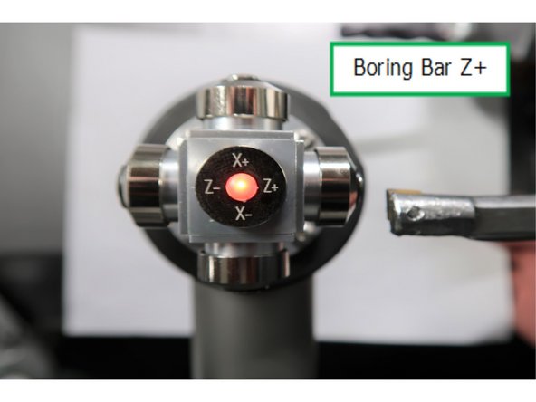
Press [Z] to begin Z+ calibration. Jog the tool tip to about ¼" from the right side of the probe button.
-
Press [CYCLE START]. The tool will touch the probe and move away. ➜ The Z value will not change — this sets the machine offset.
-
Press [Back Button] on VSK highlight back button
-
-
-
Move the current tool away from the probe to ensure full clearance.
-
Open the [Tool List] and select RIGHT_TURN/FACE_TOOL.
-
Press [OK], then press [CYCLE START] to rotate the turret.
-
Go to measure tool and select automatic
-
Press [Z] to begin Z- calibration. Jog the tool tip to about ¼" from the right side of the probe button.
-
Press [CYCLE START]. The tool will touch the probe and move away. ➜ The Z value will now update to show the offset from machine Z zero.
-
-
-
Press [X] to begin X+ calibration.
-
Jog the tool tip to about ¼" from the top side of the probe button.
-
Press [CYCLE START]. The tool will touch the probe and move away. ➜ The X value will now update to show the offset from machine X zero.
-
-
-
Move the tool away from the probe so you can return it to its home position.
-
Use a 3" Joe block between the tool and the chuck face (or spindle face). ➜ The Z value in TSM should read approximately 3.0".
-
Use feeler gage to touch the diameter of the ground pin. ➜ The X value in the tool display should read approximately 1.020", assuming a 1.000" pin and 0.010" gauge.
-


![Switch to [Act. Values MCS] on right](https://d3t0tbmlie281e.cloudfront.net/igi/trakmtsupport/UiE2RbRMacC6ZbKY.medium)
![Open the [Tool List] from the left-hand menu.](https://d3t0tbmlie281e.cloudfront.net/igi/trakmtsupport/aVGts2BHw3aJlq4i.medium)
![Press [NEW TOOL] on the right-side button panel.](https://d3t0tbmlie281e.cloudfront.net/igi/trakmtsupport/N5flG4nZgaGKWIQG.medium)
![Press [NEW TOOL] on the right-side button panel.](https://d3t0tbmlie281e.cloudfront.net/igi/trakmtsupport/JrHDcXgDGgwir4yU.medium)
![Press [NEW TOOL] on the right-side button panel.](https://d3t0tbmlie281e.cloudfront.net/igi/trakmtsupport/ymD4oAHTZlDBdeHN.medium)
![Press [SELECT TOOL] on the right-side button panel.](https://d3t0tbmlie281e.cloudfront.net/igi/trakmtsupport/pKAVUQfpuCDqiAGS.medium)
![Press [MEASURE TOOL] on the control.](https://d3t0tbmlie281e.cloudfront.net/igi/trakmtsupport/5GxpRdRMURCDUrQL.medium)
![Press [Z] to switch to the Z-axis input.](https://d3t0tbmlie281e.cloudfront.net/igi/trakmtsupport/LYHGRdRMPbChA1wj.medium)


![Open the [Tool List].](https://d3t0tbmlie281e.cloudfront.net/igi/trakmtsupport/Hqq2LdYHQxWvaKkb.medium)
![Press [MEASURE TOOL].](https://d3t0tbmlie281e.cloudfront.net/igi/trakmtsupport/2RmdRdRMQKC6ZbKY.medium)
![Press [Z] to switch to the Z-axis input.](https://d3t0tbmlie281e.cloudfront.net/igi/trakmtsupport/VAERReRMO4CJRfOr.medium)
![Press [X] to begin X- calibration.](https://d3t0tbmlie281e.cloudfront.net/igi/trakmtsupport/vpSJReRMtXK2W6xu.medium)
![Go to TSM and press [TOOL LIST] from the right VSK. Select the CUTOFF_TOOL_.125 (or your assigned cutoff tool).](https://d3t0tbmlie281e.cloudfront.net/igi/trakmtsupport/A4ByReRMmgCxoQUU.medium)
![Press [OK], then press [CYCLE START] to rotate the turret.](https://d3t0tbmlie281e.cloudfront.net/igi/trakmtsupport/Pa1GReRMGQCJvXnB.medium)
![Press [Z] to begin Z- calibration.](https://d3t0tbmlie281e.cloudfront.net/igi/trakmtsupport/bHKPRfRMpgCJRfOr.medium)
![Press [BACK] to exit manual mode.](https://d3t0tbmlie281e.cloudfront.net/igi/trakmtsupport/yErUeV1LuDV2YynV.medium)
![Press [AUTOMATIC] to enter automatic calibration mode.](https://d3t0tbmlie281e.cloudfront.net/igi/trakmtsupport/FLJMyvZ1bFYJSUCX.medium)
![Open the [Tool List] and select RIGHT_TURN/FACE_TOOL.](https://d3t0tbmlie281e.cloudfront.net/igi/trakmtsupport/DVnrZE2rOXHCFHUd.medium)
![Press [X] to begin X+ calibration.](https://d3t0tbmlie281e.cloudfront.net/igi/trakmtsupport/H1CSWcpVaTmpGAwJ.medium)
Cancel: I did not complete this guide.
2 other people completed this guide.