Introduction
This procedure is designed to guide the user in the inspection and alignment of the live tooling turret disk on the TC820LTYsi machines
-
-
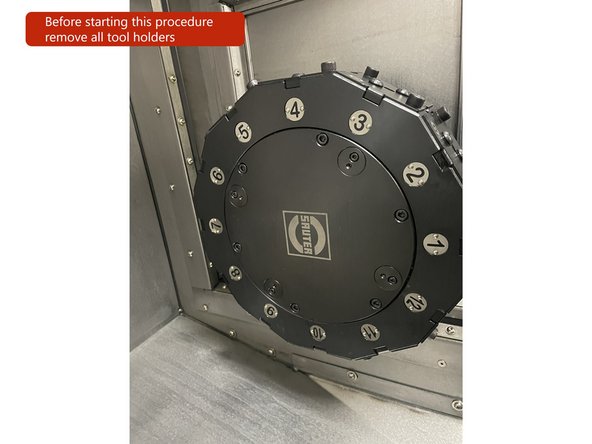
When starting this procedure for safety reasons please remove all tool holders and confirm the hydraulic pressure is at 50kg.
-
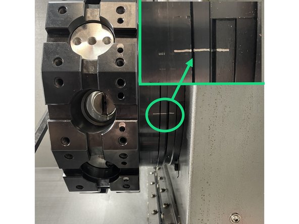
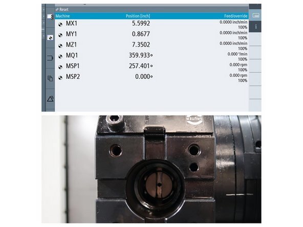
The tool disk is adjusted when the turret is at the T1 (origin) station with the disk aligned with the alignment mark lines
-
-
-
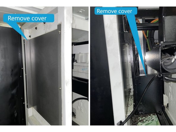
Remove the rear sheet metal cover.
-
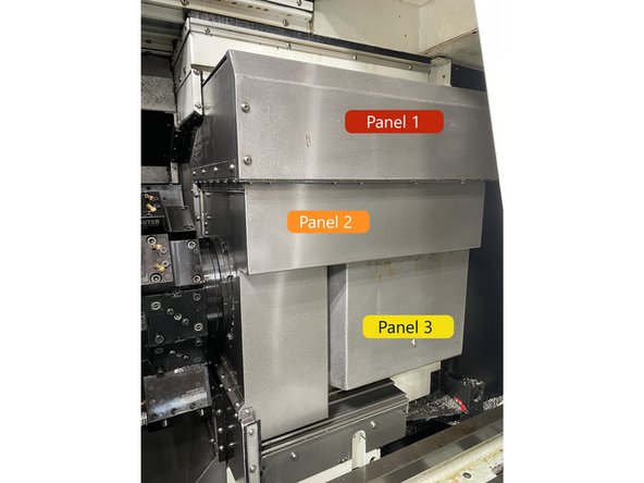
Through the front door remove upper sheet metal panel. There are 10screws in the front and there are 4 screws in the rear of the machine. (Labeled panel 1 in Photo 2)
-
Remove middle sheet metal panel (Labeled panel 2 in Photo 2)
-
Remove lower sheet metal panel (Labeled panel 3 in Photo 2)
-
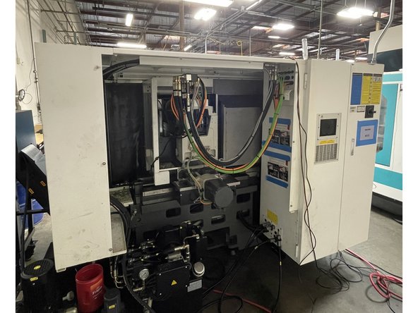
From the rear of the machine remove the internal covers shown in Photo 3.
-
-
-
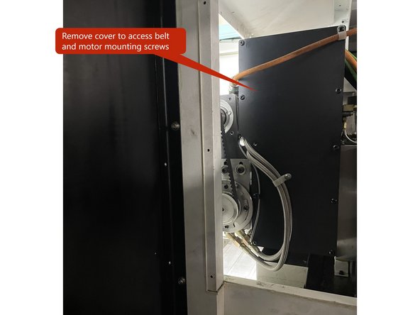
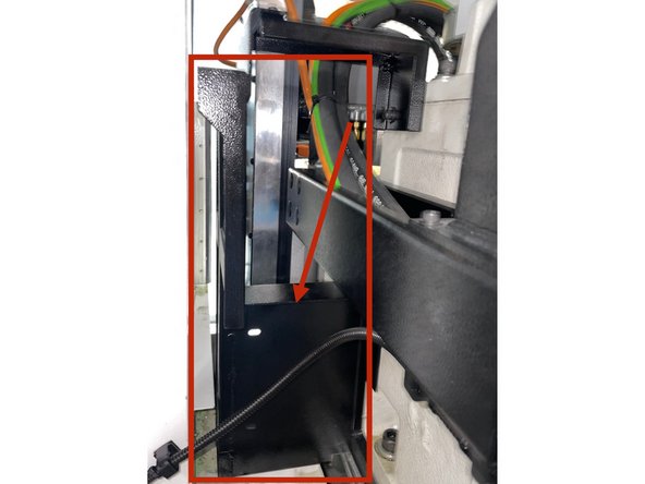
Remove cover to access the gearhead belt and motor mounting screws.
-
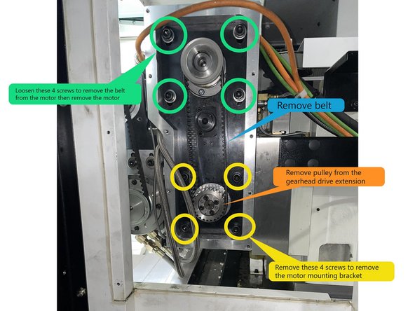
Loosen the screws circled in green to loosen and remove the belt. Once the belt is removed, remove the screws to remove the motor.
-
Caution the motor is heavy you may need another person hold the motor while you remove the screws
-
Remove the pulley from the gearhead drive extension.
-
Remove the 4 screws that mount the gearhead drive motor mounting casting to the gearhead drive extension assembly and remove the casting.
-
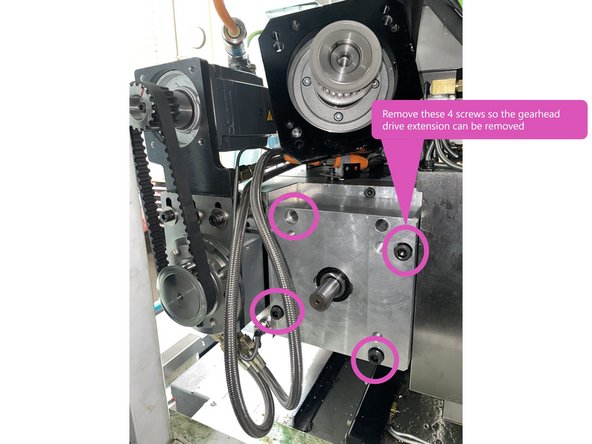
Remove the 4 screws that attach the gearhead drive extension. The gearhead drive extension is pinned and can be difficult to remove, attaching a slide hammer and lightly tapping may help get it started.
-
-
-
Remove the pulley from the gearhead.
-
The pulley is a taper lock, to remove it loosen all 8 screws and move 4 of them to the threaded holes and tighten slowly, this will release the taper lock so the pulley can be removed. See Photo 1
-
Remove the plug that covers the gearhead fixing screw and loosen the fixing screw.
-
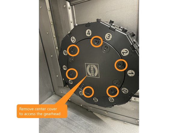
To access the gearhead mounting screws remove the front cover on the turret disk.
-
-
-
Remove the gearhead ring.
-
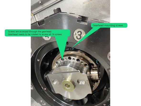
To remove the gearhead there are 16 screws that need to be removed. These screws are accessed through the front of the gearhead. The gearhead needs to be rotated to access all 16 screws. See Photo 2
-
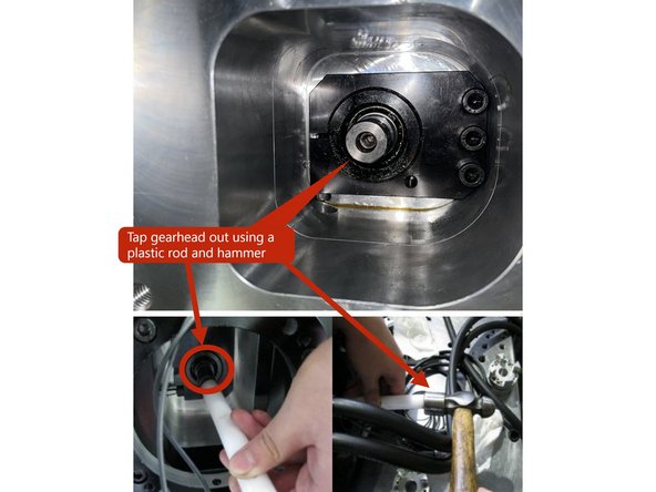
Once the gearhead fixing screw is loose and the mounting screws are removed, use a plastic rod and a hammer to slowly tap the gearhead out.
-
Use caution the gearhead is heavy, have someone on the front side to catch it as it comes out.
-
-
-
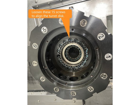
To align the turret disk loosen the 15 screws mounting the turret disk shown in Photo 1.
-
To align the turret disk, set up a dial indicator with a mag base on the tailstock slideway.
-
Install a turret alignment bar into the turret in the tool 1 location.
-
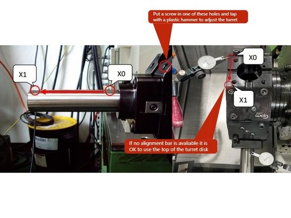
Zero the indicator on the high point of the alignment bar nearest the turret and move the X Axis towards the end of the alignment bar. The measurement should be within 0.01/90mm (0.0004"/3.5") or less.
-
You can put a screw into one of the other tool holder locations and tap it with a plastic tipped hammer to adjust the turret parallelism to the X Axis.
-
If no turret alignment bar is available you can use the top surface of the turret disk.
-
Once the turret has been aligned torque all 15 screws to 39 Nm (28ft-lbs) in a crossing pattern.
-
-
-
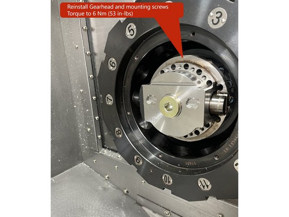
Reinstall the gearhead and all 16 screws. Torque the screws to 6 Nm (53 in-lbs) in a crossing pattern.
-
Once the turret has been aligned and the gearhead has been installed the gearhead needs to be aligned.
-
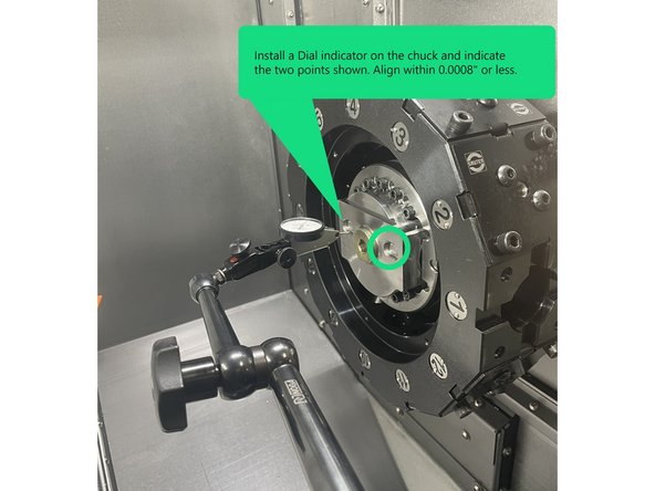
To align the gearhead install a dial indicator and a mag base on the chuck and indicate the points shown in Photo 2. The measurement should be within 0.02mm (0.0008") or less.
-
Once the gearhead has been aligned, tighten the gearhead fixing screw and reinstall the plug.
-
-
-
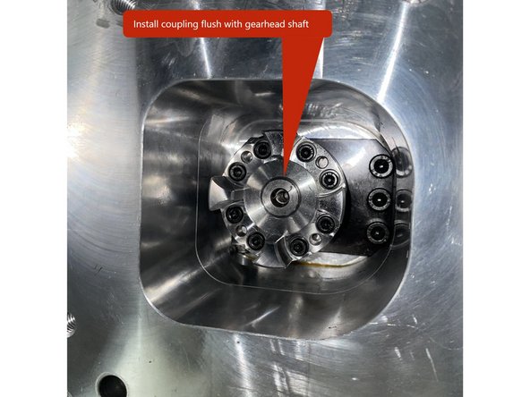
Install coupling flush with the gearhead shaft as shown in PHOTO 1. Tighten the screws in a crossing pattern to lock the taper lock to the gearhead drive shaft.
-
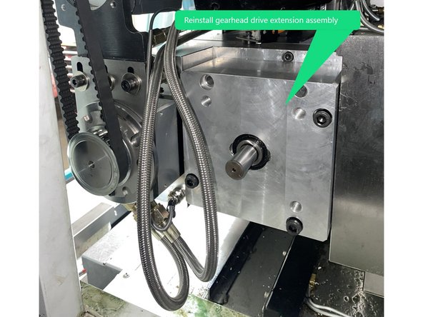
Reinstall the gearhead drive shaft extension assembly.
-
Reinstall the gearhead drive motor mounting bracket.
-
-
-
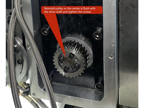
Reinstall the pulley to the gearhead drive extension so that the center is flush with the drive shaft and tighten the taper lock screws.
-
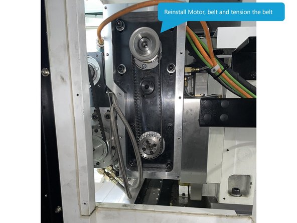
Reinstall the motor to the motor bracket then reinstall the belt. Once the belt is installed tension the belt and tighten the motor mounting screws.
-
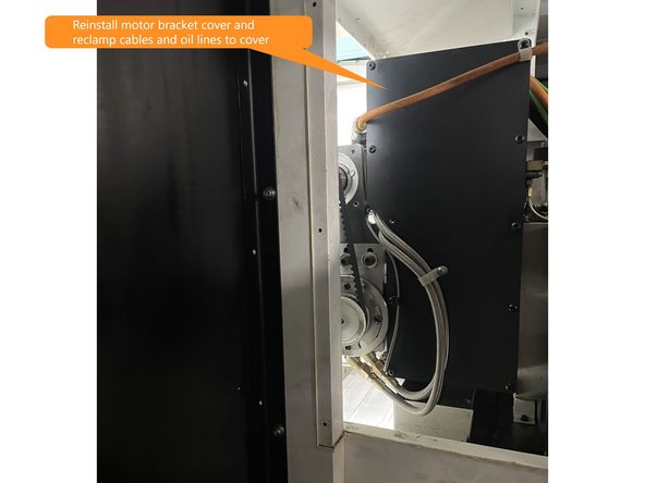
Reinstall motor bracket cover to motor bracket and reattach cables and oil lines to the cover as seen in Photo 3.
-
-
-
Before you reinstall all of the covers you need to reference the live tooling spindle. To do so use the link below to use the Reference Live Tooling Spindle procedure below:
-
-
-
-
Reinstall this inside cover.
-
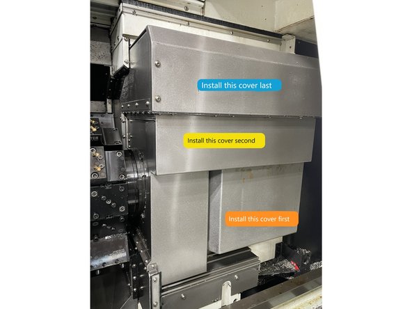
Install the lower cover first.
-
Install the middle cover second.
-
and the top cover last.
-
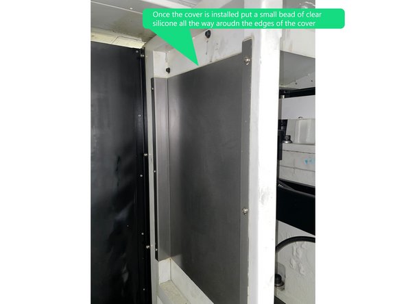
Install the cover, once installed put a small bead of clear silicone all the way around the edges of the cover.
-
Before putting silicone around the edges of this cover, clean any remaining silicone from the cover and mating surface from when the cover was removed.
-