-
-
It is vital that the turret disk be properly aligned to the spindle shaft. If the spindle shaft is not centered when the turret disk rotates around, then the turret disk must first be aligned.
-
Disk is improperly aligned to spindle shaft.
-
Disk is properly aligned, and spindle shaft is centered when disk rotates.
-
See Dozuki Guide for Turret Alignment
-
-
-
To check reference status of the S2 spindle, press [Jog] and [Ref Point] buttons. If the reference icon (pictured) is present for MSP2, then spindle is referenced.
-
If spindle is referenced and spindle slot is aligned with the slots outside of it when spindle is commanded to 0 degree, no action related to referencing is required. If spindle is referenced and spindle slot at 0 degree is not aligned with slots outside of it, proceed to Step 4- S2 Orientation for positional adjustment.
-
If spindle is not referenced, please continue to the next step to perform an initial reference. This S2 spindle must first be referenced in order to orient its position.
-
-
-
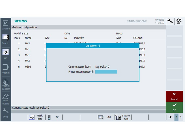
To reference the S2 spindle in order to move it, start by entering Manufacturer Password
-
-
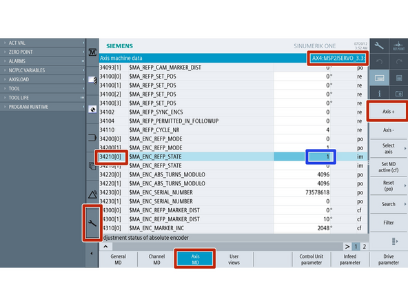
[Setup]->[Mach Data]->[Axis MD]->[Axis+ to get to MSP2]->[Search]->[34210]
-
Note: MSP2 corresponds to AX8
-
Parameter 34210 must be changed from [0] to [1]
-
-
-
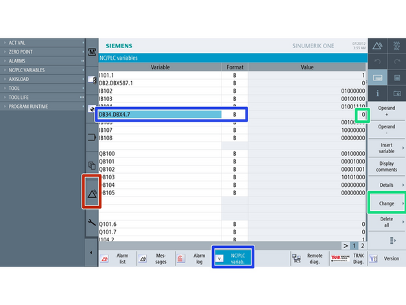
To reference S2 spindle, you will need to Press the Triangle on the left side of the screen to enter the diagnostics page. From there you can change the status of one of the bits from axis MSP2 data block.
-
Press [Diagnostics]->[NC/PLC Variable]-> Click under Variable in an empty row.
-
Enter DB38.DBX4.7 under variable. Select [B] under format.
-
Ensure that both [Jog] and [Ref Point] are active (lights above the buttons are on.)
-
Press [Change]-> change the number from 0 to1-> [Input]->[OK] to confirm bit change. The [1] value will immediately change back to [0] Then power cycle the machine.
-
-
-
The S2 spindle should now be referenced. Once powered up, go to the [Machine]->[T,S,M]
-
Select [S2]->[Orient (two arrows pointing toward a dot icon)]->[0]->[Cycle Start] to set the S2 at its orientation position. If spindle and outside slots are aligned, spindle referencing is now complete.
-
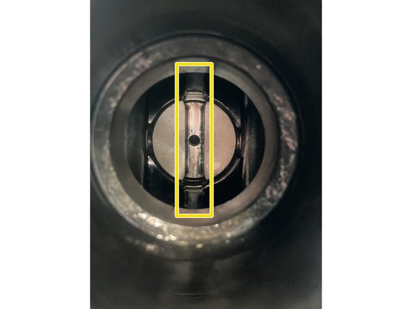
In order to function properly, the slot in S2 needs to be perfectly up and down. There are slots just outside the spindle at the top and bottom that must align with the slot in S2.
-
To align the slot, one needs to guess the angle at which the spindle needs to be positioned in the TSM screen. In this case, [S2]->[Orient]->[120]->[Cycle Start] makes the correct change.
-
With S2 orientation correct, the Spindle needs to be re-referenced. Do not move the spindle once it is aligned with the slot outside.
-
-
-
[Setup]->[Mach Data]->[Axis MD]->[Axis + (AX8:MSP2)]->[Search]->[34210]
-
Set 34210[0] to [1]->[Input]
-
Press [Diagnostics]->[NC/PLC]->[DBX38.DBX4.7]->Change]->[1] Do not press input yet
-
While [Jog] and [Ref Point] are active, press [Input]->[OK] The bit will change from 1 to 0 instantly. Then power cycle the machine.
-
-
-
Once powered back on, the initial position should still be vertical, and the S2 Spindle should be referenced, showing 0 degrees. You should see the icon when in [Machine] mode and [Jog] and [Ref Point] buttons are active.
-
To confirm, manually change the position of S2 by going to [Machine]->[T,S,M]->[S2]->[Orient]->[90]->[Cycle Start]. This should move the S2 to 90 degrees from 0 position.
-
Do the Same [S2]->[Orient]->[0]->[Cycle Start] and comfirm that the machine rotates S2 back to vertical position and reports 0 degrees. The S2 Spindle is now referenced and oriented properly.
-
Cancel: I did not complete this guide.
One other person completed this guide.


![To check reference status of the S2 spindle, press [Jog] and [Ref Point] buttons. If the reference icon (pictured) is present for MSP2, then spindle is referenced.](https://d3t0tbmlie281e.cloudfront.net/igi/trakmtsupport/rZ2Ck1dHZZAdju43.medium)


![Press [Diagnostics]->[NC/PLC Variable]-> Click under Variable in an empty row.](https://d3t0tbmlie281e.cloudfront.net/igi/trakmtsupport/cFINBdT4wv3aDbCL.medium)
![Enter DB38.DBX4.7 under variable. Select [B] under format.](https://d3t0tbmlie281e.cloudfront.net/igi/trakmtsupport/YLSFHHt5nPZ1xSY2.medium)
![The S2 spindle should now be referenced. Once powered up, go to the [Machine]->[T,S,M]](https://d3t0tbmlie281e.cloudfront.net/igi/trakmtsupport/FyXGFMGrQO16mp5h.medium)
![Select [S2]->[Orient (two arrows pointing toward a dot icon)]->[0]->[Cycle Start] to set the S2 at its orientation position. If spindle and outside slots are aligned, spindle referencing is now complete.](https://d3t0tbmlie281e.cloudfront.net/igi/trakmtsupport/MIHYjLHrg5Z3nMW6.medium)

![[Setup]->[Mach Data]->[Axis MD]->[Axis + (AX8:MSP2)]->[Search]->[34210]](https://d3t0tbmlie281e.cloudfront.net/igi/trakmtsupport/4bDsuSOsIRgmtATv.medium)
![Set 34210[0] to [1]->[Input]](https://d3t0tbmlie281e.cloudfront.net/igi/trakmtsupport/wYNhClJvDygpuc4A.medium)
![Press [Diagnostics]->[NC/PLC]->[DBX38.DBX4.7]->Change]->[1] Do not press input yet](https://d3t0tbmlie281e.cloudfront.net/igi/trakmtsupport/dpQdUIfapBXLRkay.medium)
![Once powered back on, the initial position should still be vertical, and the S2 Spindle should be referenced, showing 0 degrees. You should see the icon when in [Machine] mode and [Jog] and [Ref Point] buttons are active.](https://d3t0tbmlie281e.cloudfront.net/igi/trakmtsupport/hBitVQJUXyJlwqYm.medium)
![To confirm, manually change the position of S2 by going to [Machine]->[T,S,M]->[S2]->[Orient]->[90]->[Cycle Start]. This should move the S2 to 90 degrees from 0 position.](https://d3t0tbmlie281e.cloudfront.net/igi/trakmtsupport/cHkBQicEhEtZhe3Y.medium)