Introduction
This procedure re-establishes the absolute encoder reference, and therefore machine zero, on a TC820LTY-Ssi. It covers five servo axes: Q, X, Y, Z1 and Z2.
-
-
This procedure overwrites machine zero on X, Y, Z1 and Z2. The archive is the only way back to the machine's current state.
-
Create a complete machine archive before touching anything.
-
-
-
-
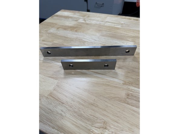
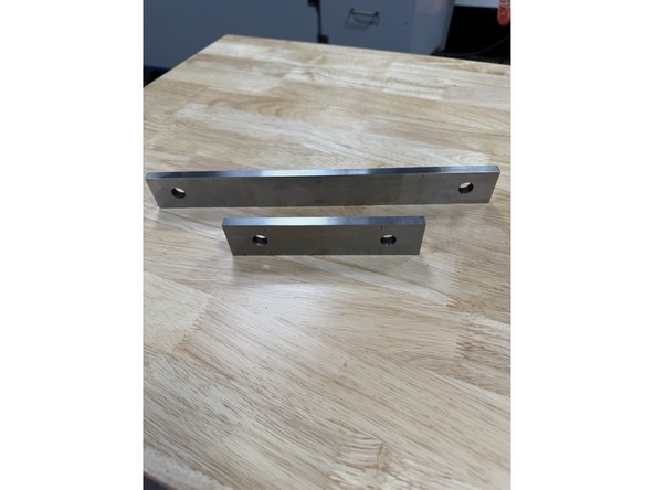
The Z1 and Z2 references use gage blocks.
-
-
-
Call TRAK Service to obtain them. They are a Shars catalog item if the shop needs its own set.
-
-
-
Press [JOG] and [REF POINT] on the MCP.
-
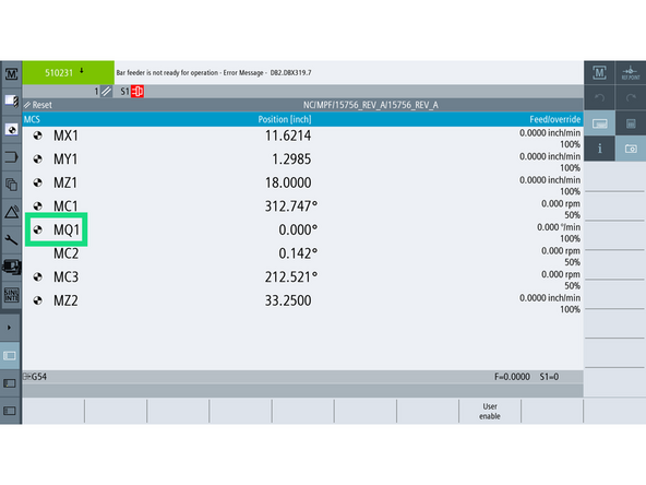
On the [Machine] screen, look for the reference icon beside each axis name: MQ1, MX1, MY1, MZ1 and MZ2.
-
The black and white circle means the axis has a reference. No icon means it does not.
-
All servo axes must show the icon before the machine is operational.
-
MC1 and MC3 are the main and sub spindles. They reference themselves the first time they rotate.
-
MC2 is the driven tool spindle.
-
The icon means only that MD34210 = 2, that the control has marked the reference valid. It does not prove the reference is correct.
-
-
-
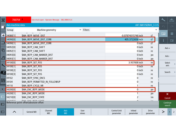
MD34090 $MA_REFP_MOVE_DIST_CORR. The calibration itself, the offset between machine zero and the encoder zero. The control writes it, not you.
-
MD34100 $MA_REFP_SET_POS. The coordinate you tell the control the axis is standing at. This is your input.
-
MD34210 $MA_ENC_REFP_STATE. Records whether this axis is referenced. Siemens calls it the adjustment status of the absolute encoder. It holds one of these values:
-
0. Not calibrated. The encoder has no reference to the physical position.
-
1. Calibration enabled. The control will accept MD34100. This is the state you set.
-
2. Calibrated. Written by the control, not by you.
-
With MD34210 = 1, the control transfers MD34100 as the absolute value and computes MD34090 from it. That is the whole mechanism this guide runs on.
-
Because MD34090 is computed from MD34100, a wrong MD34100 produces a wrong machine zero with no alarm and no icon difference.
-
-
-
You only need this step on an axis that is already referenced and has to be re-referenced. If the axis shows no reference icon, skip this step and carry on with that axis.
-
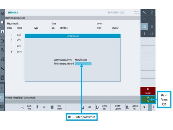
Go to [Setup] → [Mach. Data] → [Axis MD] → [Select Axis] and select the axis you are working on. Confirm the top right banner names it before you enter anything.
-
Press [Search], enter 34210, press [OK], and set MD34210[0] = 0.
-
The old reference is now gone. That axis will now accept a new one.
-
-
-
The Q axis is the rotational position of the turret.
-
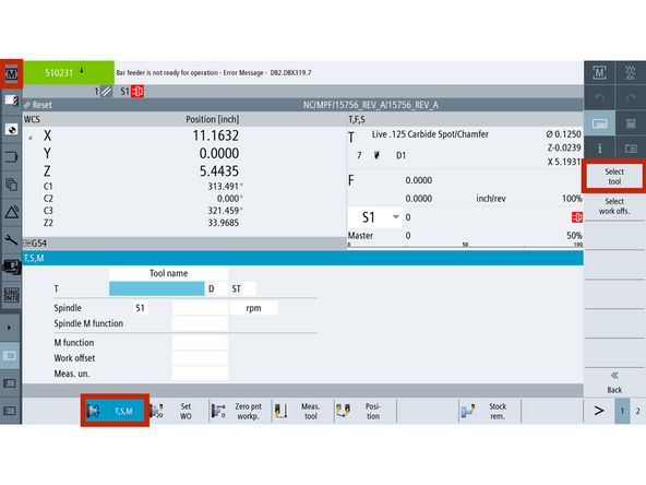
Go to [Machine] → [TSM] → [Select Tool]. Select Tool 1 and press [Cycle Start].
-
Confirm the turret has fully indexed and locked.
-
-
-
Go to [Setup] → [Mach. Data] → [Axis MD] → [Select Axis] → [MQ1/SERVO] → [OK].
-
Confirm the top right banner reads MQ1 before entering anything.
-
Press [Search], enter 34210, press [OK].
-
Set MD34210[0] = 1.
-
-
-
Go to [Diagnostics] → [NC/PLC Variable].
-
In an empty Variable row, enter DB37.DBX4.7
-
Set the Format to [B].
-
On the MCP, press [JOG] and [REF POINT].
-
Press [Change], enter 1, press [Input] → [OK]. The bit returns to 0 on its own.
-
Confirm the Q axis now shows the reference icon.
-
-
-
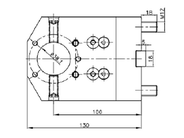
Mount TRAK Part 35723, HOLDER-BORING BAR-1.5"-BMT65, in turret Position 1.
-
Any BMT65 boring bar holder with a 100 mm center height also works.
-
The center height is in the holder designation. 35723 reads B65 BTH 18-38.1 CH100 L120. CH100 is the center height in millimeters.
-
Do not substitute a holder with a different center height. MD34100[0] for X is 100 mm because the holder is. If you do not have a 100 mm holder, stop and call TRAK Service.
-
-
-
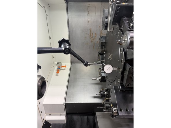
Go to [Machine] and press [Act. values MCS] to display machine coordinates.
-
Bring the centering indicator into contact with the bore of the toolholder.
-
Jog X until the tool center and the spindle center are coincident.
-
Sweep to confirm. Deviation should be under 0.001 in.
-
-
-
Go to [Setup] → [Mach. Data] → [Axis MD] → [Select Axis] → [MX1/SERVO] → [OK].
-
Confirm the top right banner reads MX1
-
Press [Search], enter 34100, press [OK].
-
Confirm MD34100[0] = 3.937008, which is exactly 100.000 mm, the center height of holder 35723.
-
If the value does not match, correct it before referencing. Whatever sits in MD34100[0] becomes the X machine coordinate when you set the reference.
-
-
-
Still on [MX1/SERVO], press [Search], enter 34210, press [OK].
-
Set MD34210[0] = 1.
-
On the MCP, turn on [JOG] and [REF. POINT].
-
Press the [X] axis button, then press [+].
-
MD34210[0] flips to 2 on its own.
-
-
-
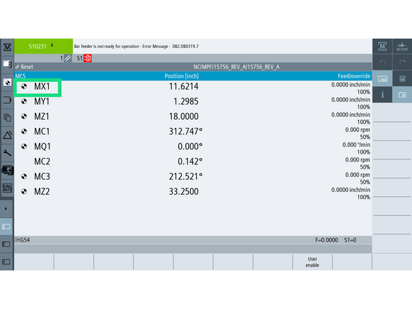
Confirm the X axis now shows the reference icon.
-
Go to [Machine] and press [Act. values MCS].
-
With the tool center still on the spindle center, confirm the X display reads 3.9370.
-
If it does not, the reference is wrong. Do not continue. Re-check MD34100[0].
-
-
-
Use turret Position 1.
-
Mount a dial indicator in the spindle with the contact point on the turret front face, the same face that will meet the gage block. Set the plunger parallel to Z, so the indicator reads how far forward the face sits.
-
Jog X back and forth across the face.
-
Deflection across the sweep should be under 0.001 in.
-
If the face is not square, stop. A tilted face contacts the gage block on one edge instead of flat, so the turret stops short of the true 6.000 in position, and that error goes straight into machine zero.
-
Remove the indicator from the spindle before continuing.
-
-
-
Measure the turret, front face to back face. This is W.
-
Measure square to both faces, at or beside turret Position 1.
-
Write W down.
-
W goes straight into machine zero. Nothing downstream catches an error in it after this step.
-
-
-
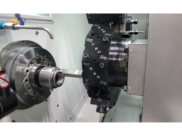
Place the 6.000 in gage block against the main spindle face.
-
Jog the turret forward until the turret front face makes light contact with the block.
-
No visible gap, but do not compress or deflect the block.
-
Leave the axis where it is. Do not move Z until the reference is set.
-
The turret front face is now 6.000 in from the main spindle face.
-
-
-
Calculate 6.000 + W/2. The 6.000 is the block. The W/2 carries the datum from the turret front face back to the turret centerline.
-
Go to [Setup] → [Mach. Data] → [Axis MD] → [Select Axis] → [MZ1/SERVO] → [OK].
-
Confirm the top right banner reads MZ1.
-
Press [Search], enter 34100, press [OK].
-
Enter the calculated value in MD34100[0].
-
-
-
Still on [MZ1/SERVO], press [Search], enter 34210, press [OK].
-
Set MD34210[0] = 1.
-
On the MCP, turn on [JOG] and [REF. POINT].
-
Press the [Z] axis button, then press [+].
-
MD34210[0] flips to 2 on its own.
-
-
-
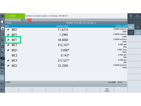
Confirm MZ1 now shows the reference icon.
-
Go to [Machine] and press [Act. values MCS].
-
With the turret front face still in contact with the block, confirm MZ1 reads the value you calculated and entered.
-
If it does not, the reference is wrong. Do not continue. Re-check the value you entered in MD34100[0].
-
-
-
Retract the turret fully clear of the working area.
-
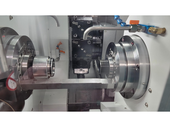
Place the 12.000 in gage block between the main spindle and sub spindle faces.
-
Jog the sub spindle forward until it makes light contact with the block.
-
No visible gap, but do not compress or deflect the block.
-
Leave the axis where it is. Do not move Z2 until the reference is set.
-
The sub spindle face is now 12.000 in from the main spindle face. There is no W/2 on this axis: the sub spindle face is the datum itself.
-
-
-
Go to [Setup] → [Mach. Data] → [Axis MD] → [Select Axis] → [MZ2/SERVO] → [OK].
-
Confirm the top right banner reads MZ2.
-
Press [Search], enter 34100, press [OK].
-
Enter 12.000 in MD34100[0].
-
-
-
Still on [MZ2/SERVO], press [Search], enter 34210, press [OK].
-
Set MD34210[0] = 1.
-
On the MCP, turn on [JOG] and [REF. POINT].
-
Press the [Z2] axis button, then press [+].
-
MD34210[0] flips to 2 on its own.
-
-
-
Confirm MZ2 now shows the reference icon.
-
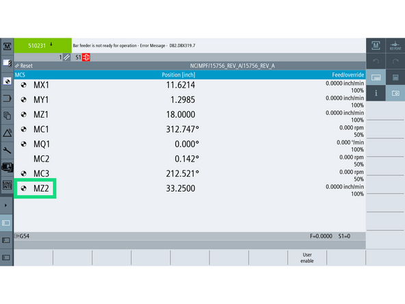
Go to [Machine] and press [Act. values MCS].
-
With the sub spindle still in contact with the block, confirm MZ2 reads 12.000.
-
If it does not, the reference is wrong. Do not continue. Re-check MD34100[0].
-
-
-
If machine zero has moved, anything calibrated against machine position is now wrong.
-
Recalibrate the tool setter. Probe calibration is machine position based.
-
-
-
-
Create a complete machine archive now that the references are set.
-
-
Send new archive to TRAK Tech Support or upload to Config Folder
-
-
![Press [JOG] and [REF POINT] on the MCP.](https://d3t0tbmlie281e.cloudfront.net/igi/trakmtsupport/oHomqeRNVroQoOcw.medium)
![Go to [Setup] → [Mach. Data] → [Axis MD] → [Select Axis] → [MQ1/SERVO] → [OK].](https://d3t0tbmlie281e.cloudfront.net/igi/trakmtsupport/neektMRN4HCJvXnB.medium)
![Go to [Diagnostics] → [NC/PLC Variable].](https://d3t0tbmlie281e.cloudfront.net/igi/trakmtsupport/JSQyq6RNFZCJvXnB.medium)
![Go to [Setup] → [Mach. Data] → [Axis MD] → [Select Axis] → [MX1/SERVO] → [OK].](https://d3t0tbmlie281e.cloudfront.net/igi/trakmtsupport/BRQhtMRNPECJvXnB.medium)
![Still on [MX1/SERVO], press [Search], enter 34210, press [OK].](https://d3t0tbmlie281e.cloudfront.net/igi/trakmtsupport/3BOWqXRNC6CJvXnB.medium)
![Go to [Machine] and press [Act. values MCS].](https://d3t0tbmlie281e.cloudfront.net/igi/trakmtsupport/oiDEqfRNVKoQoOcw.medium)
![Still on [MZ1/SERVO], press [Search], enter 34210, press [OK].](https://d3t0tbmlie281e.cloudfront.net/igi/trakmtsupport/lelNtMRNXPoQoOcw.medium)
![Go to [Setup] → [Mach. Data] → [Axis MD] → [Select Axis] → [MZ2/SERVO] → [OK].](https://d3t0tbmlie281e.cloudfront.net/igi/trakmtsupport/bRY5tNRN1yK2W6xu.medium)
![Still on [MZ2/SERVO], press [Search], enter 34210, press [OK].](https://d3t0tbmlie281e.cloudfront.net/igi/trakmtsupport/WW3AqjRN5WoQoOcw.medium)
![Go to [Machine] and press [Act. values MCS].](https://d3t0tbmlie281e.cloudfront.net/igi/trakmtsupport/1M2hqiRND4K2W6xu.medium)

Team
