Tools
Parts
No parts specified.
-
-
Before you can get started with the Turret alignment you must be sure the machine is level. If the machine is not level it's bed can become twisted and this can move the machine centers out of alignment. This can make the machine appear to be out of alignment when the machine is actually out of level. Use the below link to level the machine.
-
Link to level the machine: TRAK TC820si & TRAK TC820LTYsi - Leveling
-
-
-
Before starting this procedure for safety reasons remove all of the tool holders installed into the turret and confirm the hydraulic pressure is at 50kg.
-
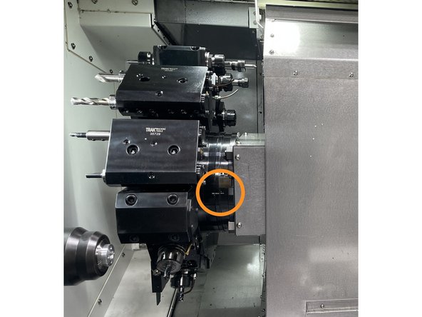
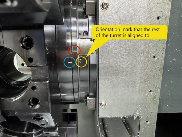
Set the turret to the number one tool location. Verify the alignment marks are lined up. If one or both of the alignment marks are out of alignment with the mark on the right side, the turret will need to be aligned. (photo shows alignment marks in line with each other) See Photo 1
-
If the center alignment mark (circled in red) doesn't line up with the mark on the right side of the turret assembly (circled in yellow), you will need to remove the Live Tooling Drive motor, Gearhead, and the turret to be able move that back into alignment. See Photo 2
-
If only the left side alignment mark (circled in blue, shown in alignment) is out of alignment you can realign the turret by loosening the turret mounting screws and rotating it back in line with the other 2 alignment marks.
-
If all 3 lines appear to be in alignment with each other the turret may still need to be aligned. You need to indicate the turret in all 3 axis to verify the alignment.
-
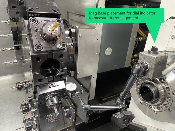
Install a dial indicator on a mag base and attach it to the Z2 spindle assembly to measure the turret in the X , Y and Z Axis. See Photo 3 for indicator placement.
-
-
-
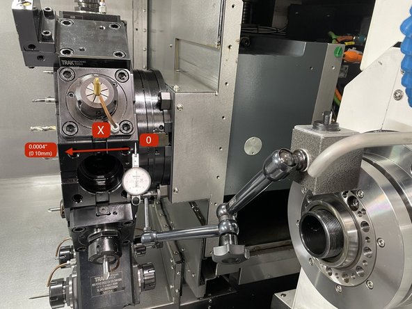
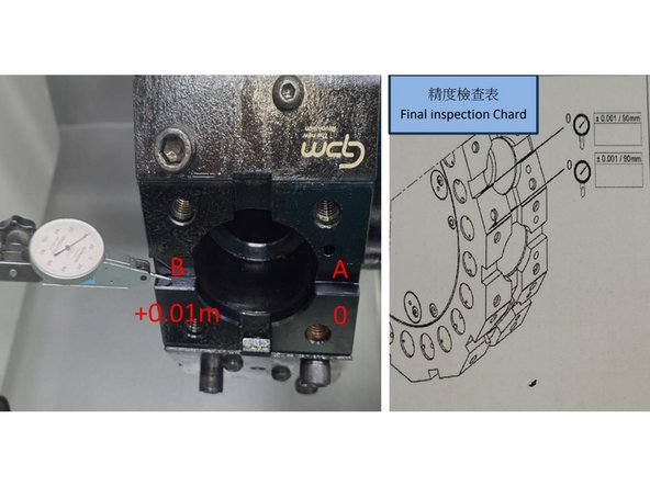
Measure the turret disk on the tool 1 tool holder mounting face. To measure the X Axis, zero on the right side and measure to the left. The spec is .0004"/3.5" (.01mm/90mm) on all 3 axis. Photo 1
-
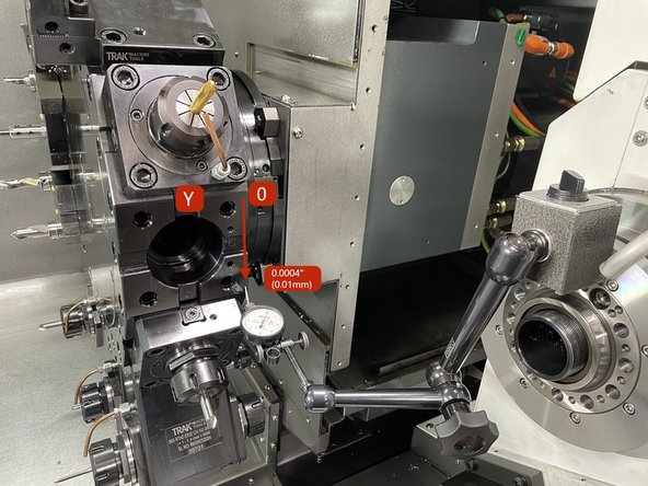
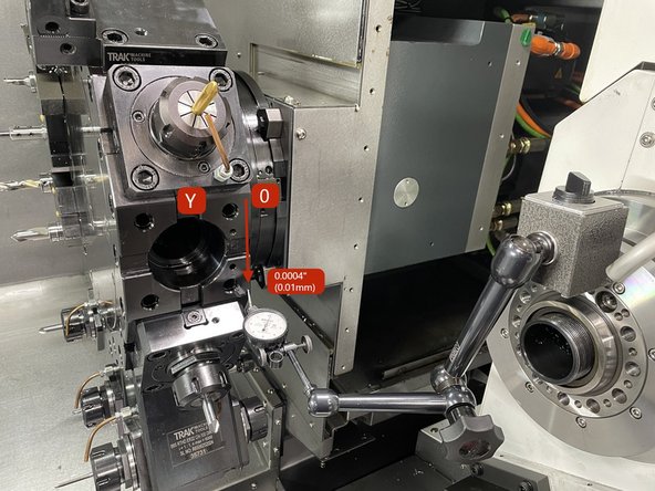
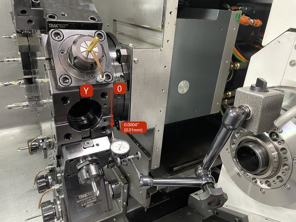
To measure the Y axis zero at the top and measure down. Photo 2
-
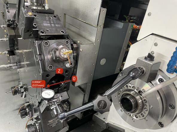
To measure the Z Axis zero the indicator on the right side of the tool holder alignment face and measure to the left. See Photo 3
-
If it is determined that the turret is out of alignment the following procedure will assist you in getting it back into alignment.
-
-
-
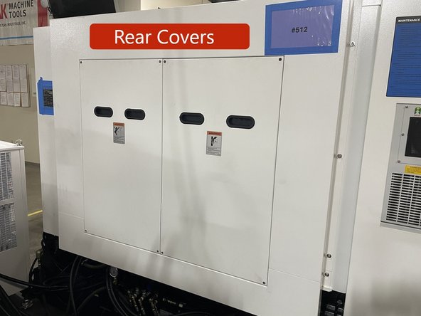
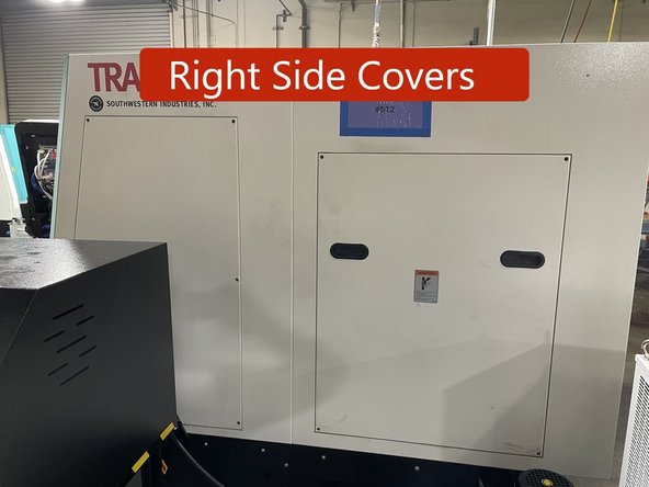
To access the turret there a few covers that need to be removed. The rear 2 covers and the 2 covers on the right side of the machine need to be removed. Photos 1 and 2
-
-
-
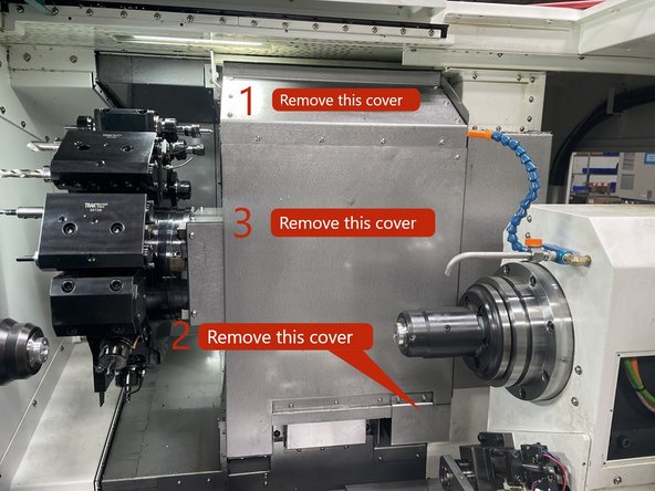
Next you need to remove the inner covers on the turret assembly.
-
Remove the screws on the upper inner cover and remove it. Then remove the lower front cover then remove the front cover. Remove them in the order of the numbers 1, 2, and 3. See Photo
-
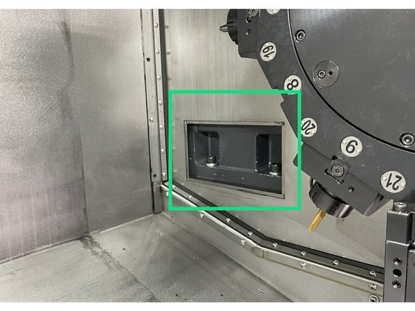
Move the X Axis all the way forward and the Z all the way to the right. Be careful when moving the X and Z Axis that they don't hit the Sub Spindle. Remove the left inside cover.
-
Remove the right side cover from the right rear side of the machine.
-
-
-
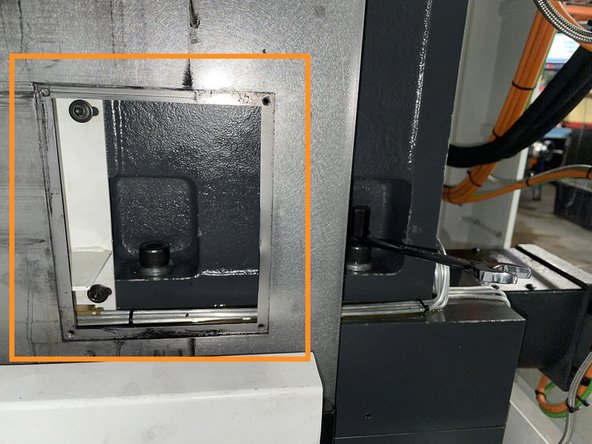
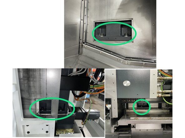
To prep for the horizontal alignment loosen the 5 screws that attach the Y Axis column to the X Axis and retorque to 7 ft-lbs (100kgf). See photo 1 for screw locations.
-
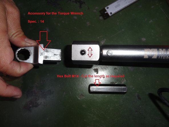
Use a special torque wrench with a 14mm box end wrench adapter and a short cut 14mm hex driver to loosen the 5 screws that attach the Y Axis column to the X Axis. See photo 1 for locations and photo 2 for tools.
-
-
-
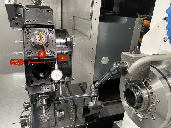
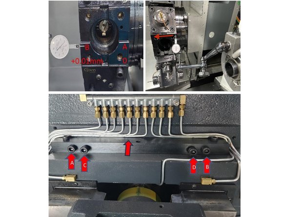
Set up your indicator to measure the horizontal accuracy (X Axis). Zero the indicator on the right side of the tool holder mounting surface and measure to the left. See Photo 1
-
To adjust the Horizontal accuracy use the screws marked A, B, C & D below in photo 2. You can loosen A to adjust C or loosen B to adjust D to bring the horizontal accuracy of the turret back to within 0.0004"/3.5" (0.01mm/90mm).
-
After finishing the horizontal adjustment of the Y axis column, torque all screws to 187 ft-lbs (2600kgf). Then, recheck the accuracy to confirm that it didn't change when the screws were tightened.
-
-
-
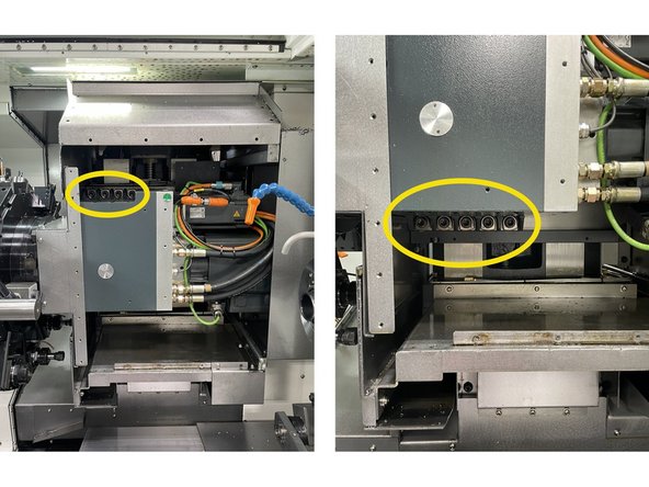
To prep for the vertical alignment loosen the 4 upper and 5 lower screws and retorque to 7 ft-lbs (100kgf). See Photo 1 for screw locations.
-
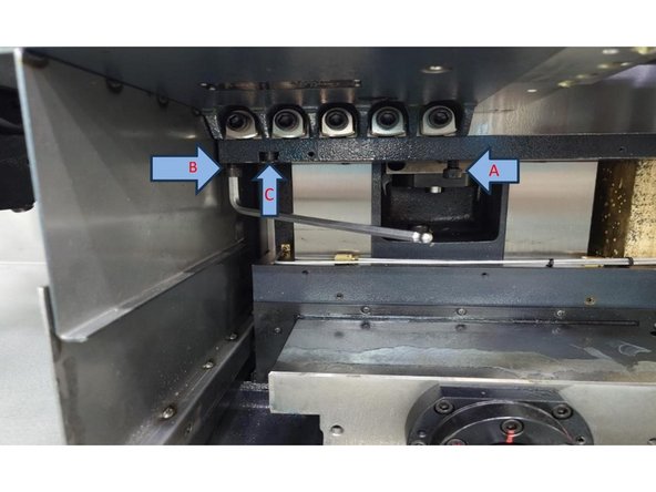
Set up your indicator to measure the vertical accuracy (Z Axis). Zero the indicator at point A and move the Z Axis to point B. See Photo 2
-
To adjust the vertical accuracy use the screws marked with the arrows in Photo 2. You can loosen C to adjust B or tighten C to adjust A to get the accuracy back to within 0.0004"/3.5" (0.01mm/90mm).
-
After finishing the vertical adjustment of the turret assembly, torque all of the screws to 72 ft-lbs (1000kgf). Then, recheck the accuracy to confirm that it didn't change when the screws were tightened.
-
-
-
There are 2 methods of realigning the turret in the Y Axis, they are dependent on if the center disk is out of alignment with the main disk or not. The following steps will guide you through both methods.
-
Before getting started with either method of realigning the turret verify the turret is in the tool one position.
-
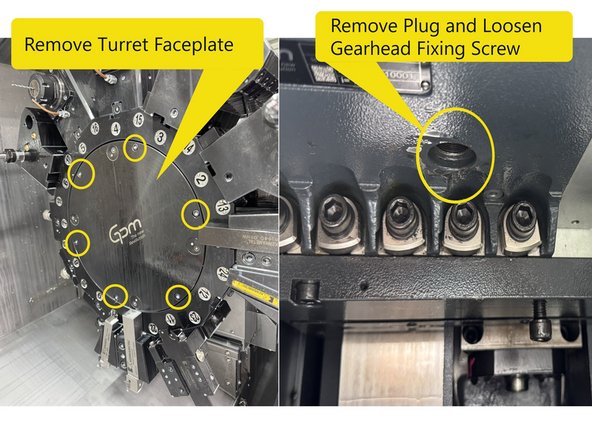
To adjust the turret in the Y Axis you need to remove the turret face plate to access the turret mounting screws. You also will need to loosen the Gearhead fixing screw so that the gearhead can be rotated 360 degrees to be able to access all of the turret mounting screws. See Photo 2
-
If the turret ring (center disk) needs to be realigned skip to step 12
-
-
-
Method 1: Alignment of the turret without having to realign the center disk (turret ring).
-
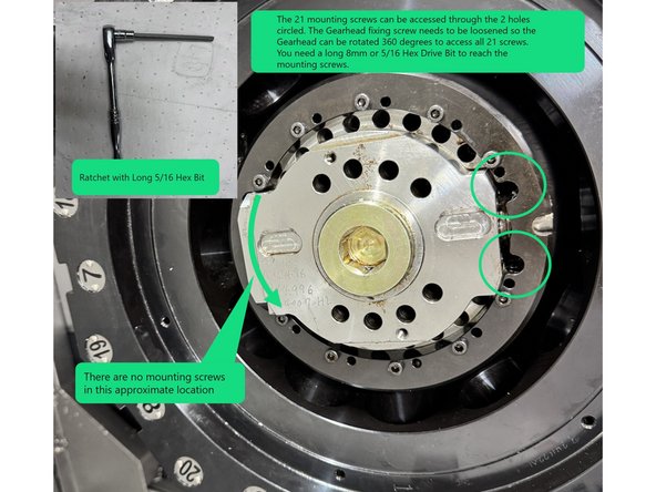
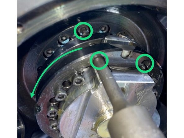
There are 21 mounting screws in the turret that need to be loosened in order to align the turret in the Y Axis. They are located behind the gearhead. There is an area where there are no mounting screws, it is marked on the photo with a curved arrow. See Photo 1
-
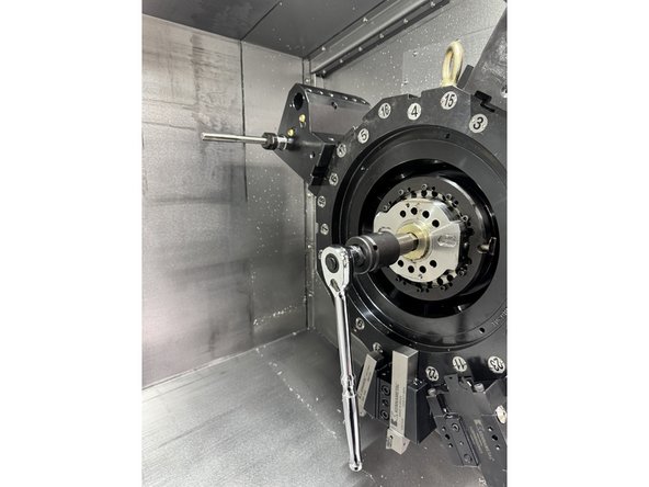
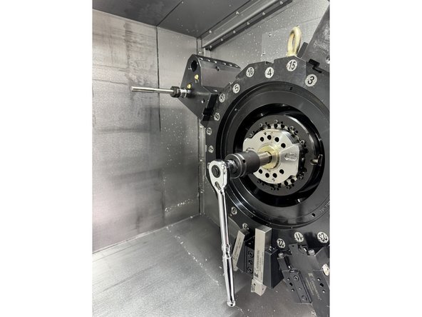
To loosen the turret mounting screws located behind the gearhead you will need a long 8mm or 5/16" Hex Drive Bit and a ratchet to access the screws through the gearhead access holes. The gearhead will need to be rotated 360 degrees to access all of the screws.
-
Do not use a long 8mm ball-end hex bit to loosen or tighten the turret mounting screws.
-
If the Gearhead can't be easily rotated by hand with the Gearhead fixing screw loose, you can use a 22mm Allen wrench or 22mm Hex bit and a ratchet to rotate it 360 degrees to loosen all 21 of the mounting screws.
-
-
-
Once all of the screws are loosened the turret can be rotated back into tolerance by tapping it with a plastic tipped hammer. You may want to put a screw into one of tool holder mounting holes to tap with the plastic tipped hammer.
-
To measure the Y Axis accuracy set up a dial indicator and zero it at the top of the tool holder mounting surface. Raise the Y Axis to measure as shown in Photo 1. The Max error is 0.0004"/3.5" (0.01/90mm).
-
Once the turret is back in alignment 0.0004"/3.5" (.01mm/90mm) torque the 21 mounting screws to 55ft-lbs of torque. Recheck the alignment to verify it didn't change when the screws were torqued.
-
-
-
Method 2: Turret disk and coolant disk alignment. This method requires the removal of the turret disk to be able to realign the coolant disk.
-
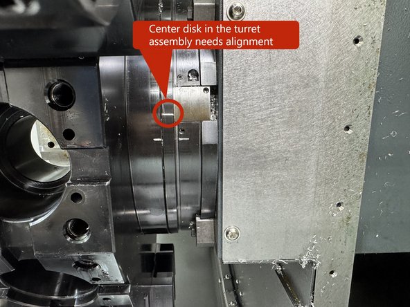
If it is determined that the turret needs to be removed in order to realign the center disk in the turret assembly, this procedure will guide you through that process. Be sure that the turret is in the tool one location when you check if the alignment marks are in line. Photo 1
-
To remove the turret the gearhead motor needs to be removed first, then the Gearhead, and then you can remove the turret To do that there some more covers that need to be removed. You will also need to disconnect the roller shade.
-
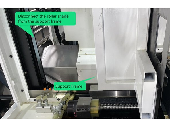
First disconnect the roller shade from the support frame. Photo 2
-
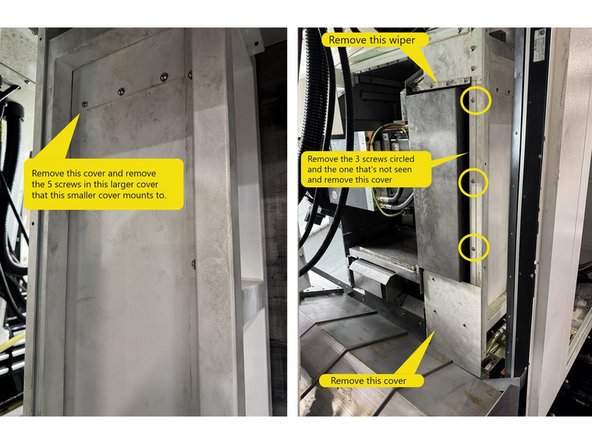
Next remove the small upper cover. Then remove the wiper, the lower cover and the larger cover shown in Photo 3.
-
-
-
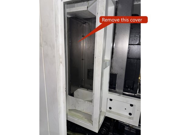
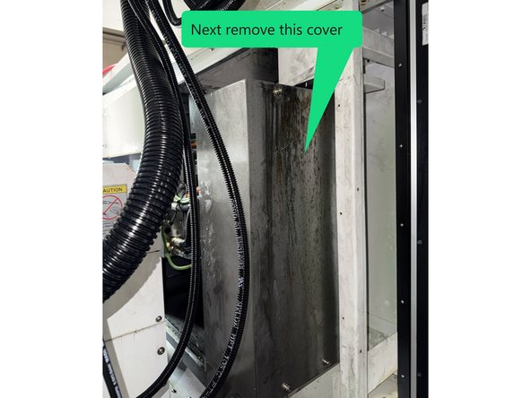
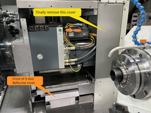
There is a stainless steel rectangular box that covers the back of the Gearhead Motor, this needs to be removed. It comes apart in 3 pieces.
-
First remove this cover.
-
Next remove this cover.
-
Finally remove this cover.
-
You will also need to remove the cover over the front of the X Axis Ballscrew.
-
-
-
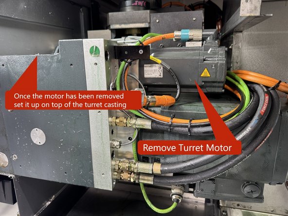
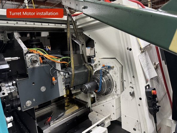
The next step in the removal of the turret is removing the Turret Motor. It is mounted to the turret casting by 4 M6 SHCS. You can leave the motor and encoder cables connected, just cut the zip ties attaching the cables to the coolant line and set the motor on top of the turret casting.
-
Now move the X Axis to the front soft limit and the Z to the soft limit closest to the Main Spindle. Move the Sub Spindle to the max travel away from the Main Spindle.
-
If there is a chuck or collet chuck adapter installed to the sub spindle remove it before removing the Live Tooloing Motor.
-
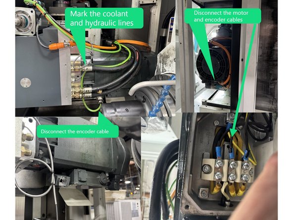
Mark the coolant and hydraulic lines so they can be reinstalled in the same place when reassembling. Remove the coolant and hydraulic lines.
-
Now power the machine off. Remove the encoder and logic cables. Remove the wiring cover to access the motor power wires. Mark the wires so they can be put back in the same terminals so the phase remains the same.
-
Note: Once you remove the cables from the Gearhead Motor you will not be able to move the machine under power.
-
-
-
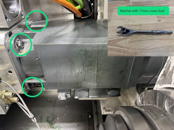
Now loosen the (4) 17mm Hex Head screws that mount the Gearhead Motor. To access the 2 rear screws, you will need a 17mm Crows foot and a ratchet to get them loose. At this time snug the front 2 screws and remove the rear 2 screws.
-
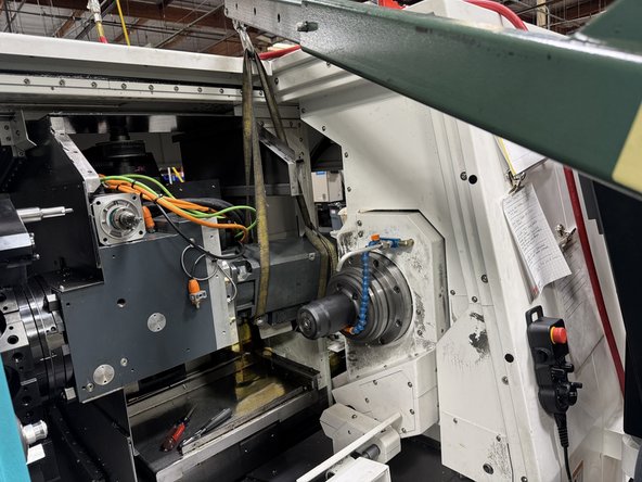
Install a strap around the motor and attach it to a crane or some other lifting device. Once the motor is supported by the lifting device remove the front 2 mounting screws and slowly remove the motor from the turret.
-
Caution: The Motor is Heavy do not try to remove without a lifting device of some kind.
-
Using a ratchet and an 8MM or 5/16" Hex Driver move the Z Axis to the hard stop farthest from the main spindle. Be careful and watch that the turret doesn't hit the Sub Spindle. If it is too close use the ratchet to move the X Axis back so that the turret doesn't hit the Sub Spindle when moving it back to the Z Axis hard stop.
-
-
-
To remove the Gearhead you first need to remove the coupling attached to it.
-
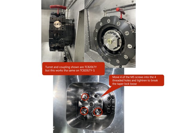
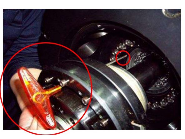
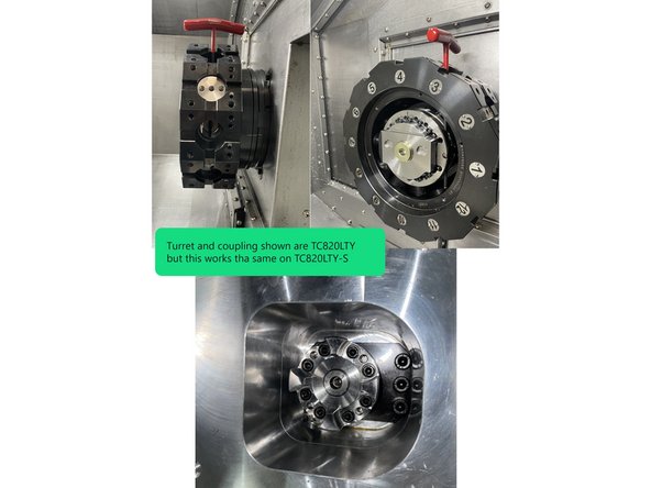
You can now access the coupling on the Gearhead through the right side cover. Put a long M4 or M5 T-Handle down through the Turret and into the Gearhead drive shaft to prevent it from rotating when you are loosening the coupling screws.
-
Once all of the coupling screws are loose, move 4 of the M5 screws into the threaded holes in the coupling and tighten to break the taper lock loose. Then remove the coupling. See Photo 1
-
Be sure to remove the T-Handle used to prevent the gearhead drive shaft from rotating before trying to remove the Gearhead.
-
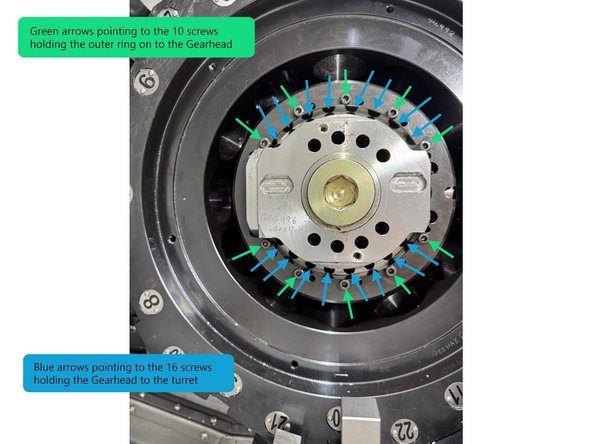
To remove the Gearhead there are 10 M5 screws that attach the outer ring and 16 M5 screws that attach the gearhead to the turret. Remove the outer ring and then remove all 16 screws that attach the Gearhead to the turret. You will need a long M4 T-Handle to get to the 16 screws that attach the gearhead to the turret. See Photo 2 for locations.
-
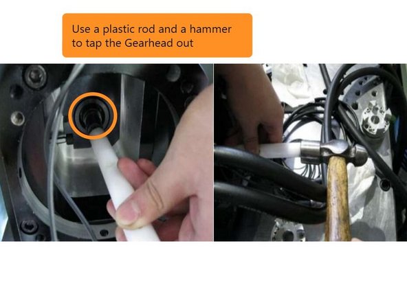
Once all of the screws have been removed the Gearhead can be tapped out with a hammer and a plastic rod. The Gearhead is a little heavy, have someone in the front of the turret to catch it as it comes out of the turret to prevent it from falling into the machine and possibly doing damage.
-
-
-
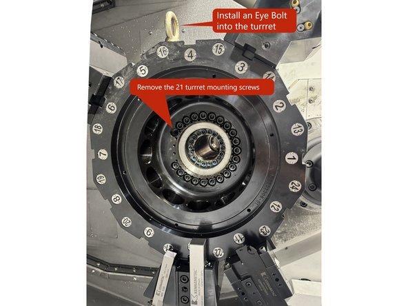
Now that the Gearhead has been removed, the Turret Disk can be removed. Install an Eye bolt into the Turret Disk so that you can attach a crane or other lifting device.
-
There are 21 M10 screws that attach the Turret Disk to the Turret Assembly. Support the Turret Disk with your lifting device and remove the 21 screws. Once the screws have been removed tap the Turret Disk out with a plastic tip hammer or mallet.
-
Caution: The Turret Disk is Heavy do not try to remove without a lifting device of some kind.
-
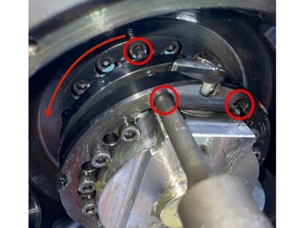
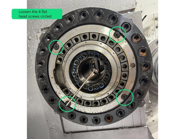
Now that the Turret Disk has been removed, loosen the 4 flat head screws circled in photo 2.
-
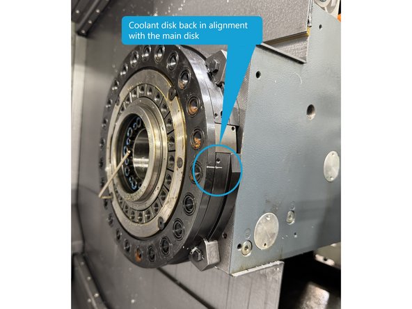
With the 4 screws loose, the center ring can be rotated to align the mark on it with the mark on the right side ring of the Turret assembly. Once the disk is aligned retighten the screws. See Photo 3
-
With the turret ring removed from the coolant disk, now is a good time to inspect the O-Rings in the turret disk and replace if needed.
-
-
-
Once the turret ring is back in alignment you can now reinstall the turret disk.
-
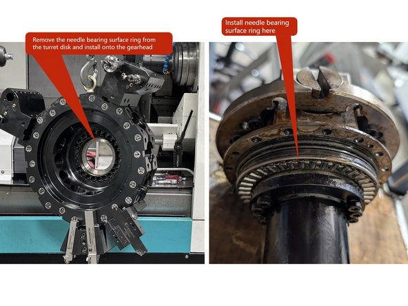
Before you install the turret disk remove the needle bearing surface ring from inside of the turret disk and install it on the Gearhead.
-
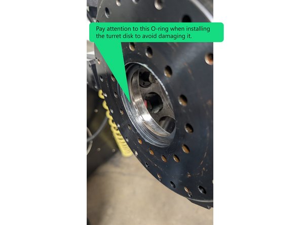
Lift the turret disk with the lifting device and align it with the turret, then slowly press the disk onto the turret watching that the large O-ring in the center of the turret disk doesn't get knocked out or pinched between the turret and the disk
-
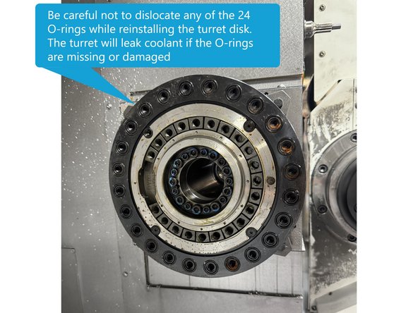
Be careful when reinstalling the turret disk that you don't knock out or dislocate any of the 24 smaller O-Rings. The turret disk to coolant disk connection points will leak coolant if the O-Rings are missing or not aligned correctly.
-
-
-
Now that the turret disk has been reinstalled, reinstall the Gearhead.
-
When reinstalling the Gearhead use a T-Handle wrench (2.5mm or 3mm) to go through the fixing screw access hole, the fixing screw flange hole on the gearhead and into the turret disk hole to align the gearhead to the turret disk. See Photo 1
-
Once the gearhead is installed and aligned with the mounting holes in the turret disk, install the 16 M5 screws and torque to 53in-lbs.
-
Reinstall the coupling to the Gearhead Drive Shaft, there is a snap ring on the drive shaft that acts as a stop for the coupling. Install the coupling until it makes contact with the snap ring and tighten the coupling.
-
Put a long M4 or M5 T-Handle down through the Gearhead and into the drive shaft to prevent it from rotating when you are tightening the coupling screws. Leave the T-Handle in place, you want to prevent the drive shaft from rotating when you are reinstalling the motor in the next step.
-
-
-
Move the Z Axis to the far left and the X Axis as far forward as possible to prep for the installation of the Gearhead motor.
-
Lift the motor with a crane or other lifting device, align the coupling on the motor with the coupling on the drive shaft and slowly move the motor back into the turret assembly. Once the motor is back into the turret install the 4 mounting screws and tighten.
-
You need to use a 17mm crows foot and a ratchet to tighten the 2 rear screws.
-
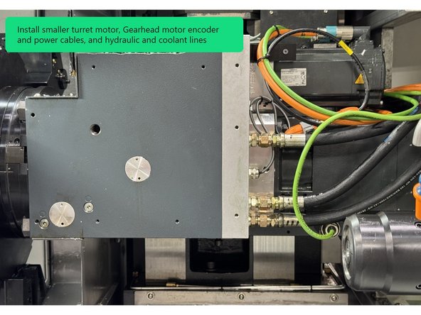
Now that the Gearhead motor has been installed, reinstall the smaller turret motor to the turret casting. Next reinstall the motor power and encoder cables to the gearhead motor. Then install the coolant and hydraulic lines to the turret.
-
-
-
Verify all of the cables, coolant and hydraulic lines are connected and power the machine up.
-
Set up a dial indicator on the Main Spindle. With the Y Axis at the bottom of travel zero the indicator at the top of the tool 1 mounting face. See Photo
-
Jog the Y Axis up, measuring the face of the tool 1 mounting surface. Adjust the turret disk to achieve an error of no more than 0.0004"/3.5" (0.01mm/90mm). You may need to use a plastic tipped hammer to tap the turret disk into alignment.
-
Once the turret disk has been aligned torque the 21 mounting screws to 55ft-lbs. You will need to rotate the Gearhead 360 degrees to access all 21 of the turret mounting screws.
-
If the Gearhead can't be easily rotated by hand with the Gearhead fixing screw loose, you can use a 22mm Allen wrench or 22mm Hex bit and a ratchet to rotate it 360 degrees to loosen all 21 of the mounting screws.
-
After all of the screws have been torqued verify the turret alignment didn't change when you tightened the screws.
-
-
-
Once the turret has been aligned and the gearhead has been installed the gearhead needs to be aligned.
-
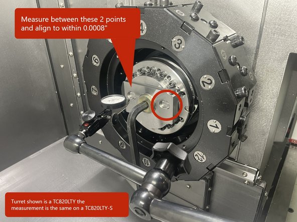
To align the gearhead install a dial indicator and a mag base on the chuck and indicate the points shown in Photo 1. The measurement should be within 0.02mm (0.0008") or less.
-
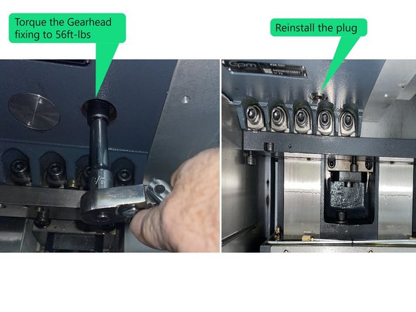
Once the gearhead has been aligned, torque the gearhead fixing screw to 56ft-lbs and reinstall the plug.
-
-
-
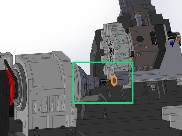
Once the horizontal and vertical accuracy has been aligned you need to check the Spindle to turret centerline concentricity. To do this install a 5C Collet Chuck with a 0.375" High Accuracy Collet.
-
Clean the 5C Collet Chuck with WD-40 or an equivalent, and use a fine grit deburring stone to check for dinks or high spots on the mounting and measuring faces.
-
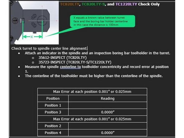
Attach an inspected Boring Bar Tool Holder to the Turret, the offset between the turret face and center of the bore must be known. Install the 5C collet chuck onto the spindle face. Using a high accuracy 5C Collet install a Co-Axial dial indicator so it is centered on the Spindle rotary axis.
-
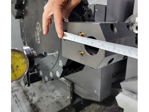
Position the indicator so it is measuring on the ID of the boring bar holder and adjust the axis so the turret is close to the centerline of the spindle. The X-Axis should be at the value equal to the offset between the turret face and the center of the bore on the Boring Bar Holder. The Y-Axis should be positioned on 0.
-
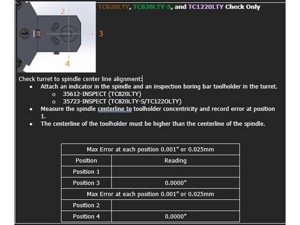
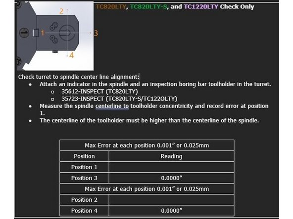
Starting with the Co-Axial indicator set to Zero at position 3 (see photo 3), rotate the spindle 360° and record the indicator movement at positions 1, 2, and 4.
-
The maximum permitted error is 0.001" [0.025mm]. The centerline of the toolholder in the Y Axis must be higher than the centerline of the spindle.
-
Repeat check at turret position 7.
-
-
-
To align the turret centerline with the main spindle move the X and Y axis positions until the centerline of the tool holder bore is within spec of the spindle centerline.
-
Starting with the digital indicator set to Zero at position 3, rotate the spindle 360° and record the indicator movement at positions 1, 2, and 4.
-
The maximum permitted error is 0.001" [0.025mm]. The centerline of the toolholder in the Y Axis must be higher than the centerline of the spindle.
-
Verify parameter settings MD 34100[0]:
-
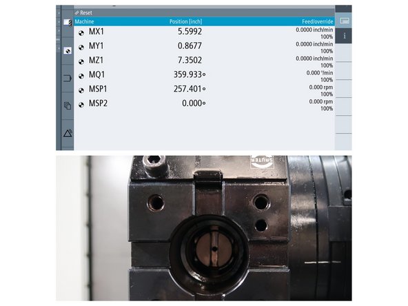
X-Axis MD 34100[0]: Set to the value between the turret mounting face and the centerline of the tool holder bore. In this case it is 100mm as shown in photos 2 and 3.
-
Y-Axis MD 34100[0]: Set to 0.
-
Change parameter setting MD 34210[0] to 1 for the X and Y Axis. Press Jog -> Ref Point on the MCP and set the Feed Override to 0%.
-
Press and hold the "X" and "+" buttons on the MCP to reset the X-Axis position. Press and Hold the "Y" and "+" buttons on the MCP to reset the Y-Axis position.
-
-
-
To reference the live tooling spindle use the link below:
-
-
-
-
Once all of the alignments have been completed and the screws have been torqued you can reinstall all of the covers that were removed to do this job in the reverse order that they were removed in.
-
![The maximum permitted error is 0.001" [0.025mm]. The centerline of the toolholder in the Y Axis must be higher than the centerline of the spindle.](https://d3t0tbmlie281e.cloudfront.net/igi/trakmtsupport/MCWyXNRNXHCJvXnB.medium)

Team
