Introduction
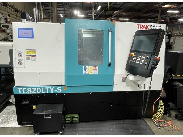
This procedure will show the user how to Realign the Main Spindle on the TC820LTY-S. It can be used to realign in case of a spindle replacement, a crash, or both. In case of a crash there will be Links to realign the Turret and Sub-Spindle, because one or both of them may have gotten knocked out of alignment as well.
Parts
No parts specified.
-
-
Before you can get started with the Main Spindle alignment you must be sure the machine is level. If the machine is not level it's bed can become twisted and this can move the machine centers out of alignment. This can make the machine appear to be out of alignment when the machine is actually out level. Use the below link to level the machine.
-
Link to level the machine: TRAK TC820si & TRAK TC820LTYsi - Leveling
-
-
-
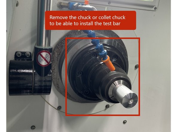
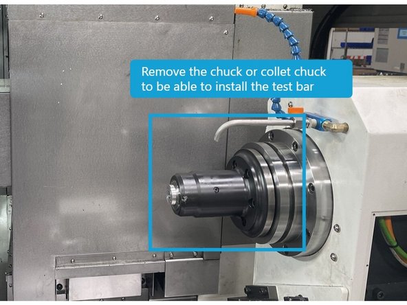
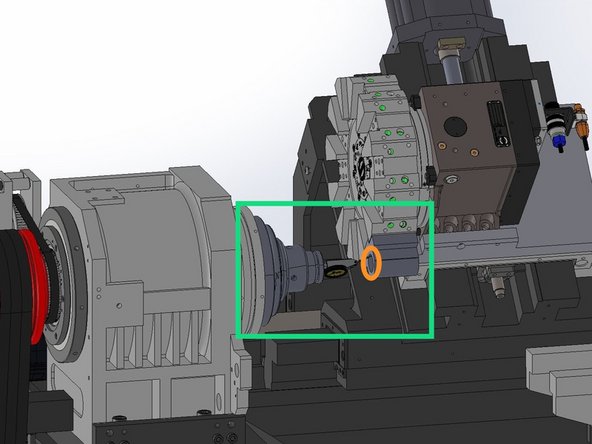
To check the alignment of the main spindle you first need to remove the chuck or collet chuck on the main spindle. Then once removed close the chuck. The test bar must not be up against the draw tube of the hydraulic chuck assembly. It must be against the spindle face.
-
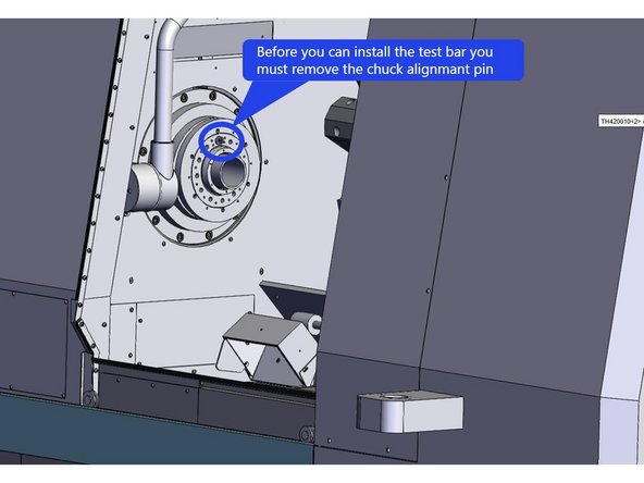
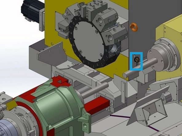
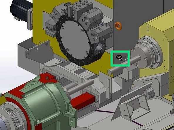
Before you can install the test bar you will need to remove the alignment pin in the spindle face. See Photo.
-
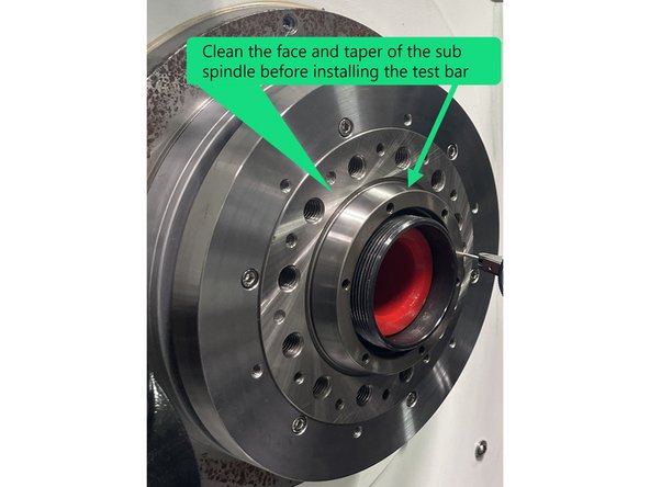
Next you need to clean the spindle face and taper and check for any debris stuck to it. Then check for any knicks or dings and remove them with a fine stone (1000 or 1500 grit). Do the same to the test bar mounting surface, then wipe the spindle face and test bar clean with a soft cloth and install the test bar to spindle face.
-
-
-
Before getting started first verify that the Main Spindle needs to be realigned.
-
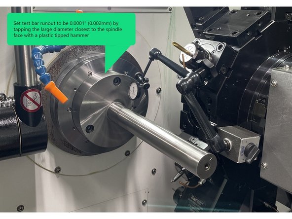
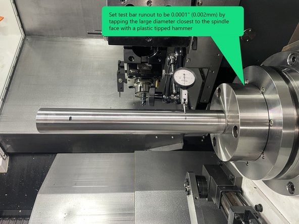
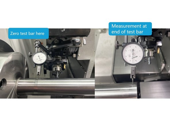
Install a dial indicator to the turret and move the Z1 axis so that the indicator can measure the test bar closest to the Main Spindle face. Set up the indicator to measure the spindle runout.
-
To align the test bar, measure the runout near the spindle face and adjust to 0.0001" or better (0.002mm). Use a plastic tipped hammer to tap test bar to achieve the desired runout. Torque the test bar mounting screws to 86 in-lbs (100 kgf.cm) and then again to 177in-lbs (200 kgf.cm) . Check runout to verify it didn't change when torqued.
-
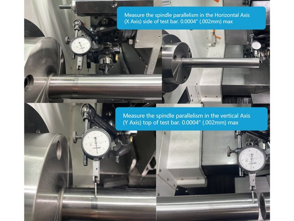
Set the indicator to measure the horizontal accuracy (side of test bar). Zero the indicator closest to the spindle face and move the Z1 Axis (turret) towards the end of the bar to measure the horizontal accuracy. This should measure no more than 0.0004" (0.01mm).
-
Next set up the indicator to measure the vertical accuracy (top of the test bar). Zero the indicator closest to the spindle face and move the Z1 Axis (turret) towards the end of the bar to measure the vertical accuracy. It should not measure any more than 0.0004" (0.01mm). See Photo
-
If either of the above measurements are above 0.0004" (0.01mm) the main spindle needs to be adjusted.
-
If it is determined that the Main Spindle is out of alignment the following procedure will assist you in getting it back into alignment.
-
-
-
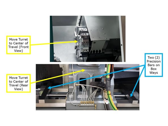
To do the alignment of the TC820LTY-S Main Spindle, a few covers need to be removed. The next few points in this step will show which covers need to be removed.
-
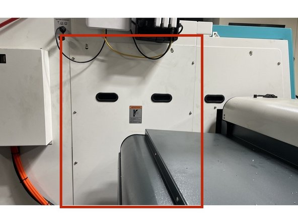
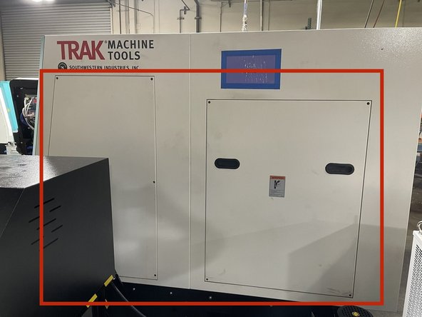
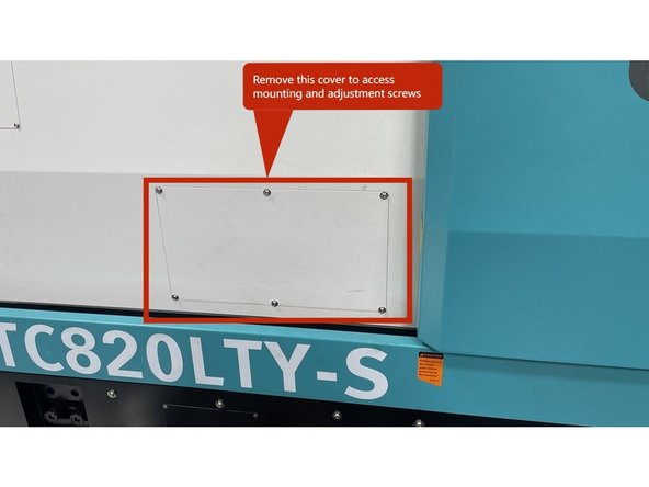
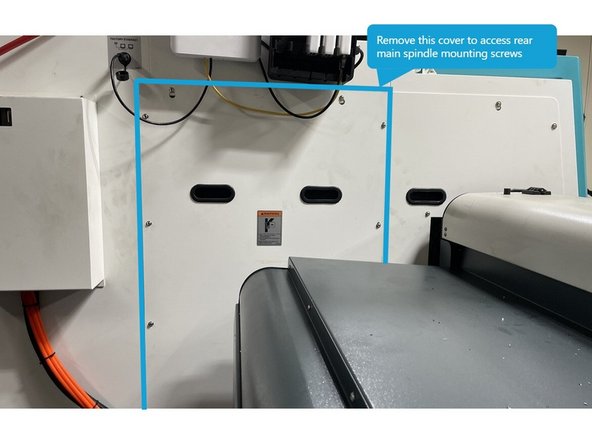
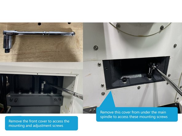
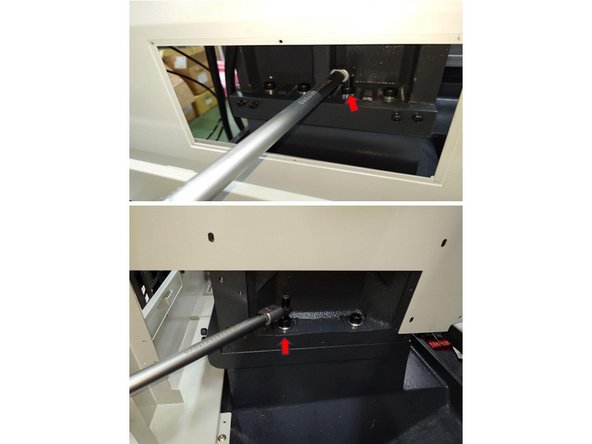
To access the adjustment and four (4) mounting screws on the front side of the machine remove the cover shown in photo 1.
-
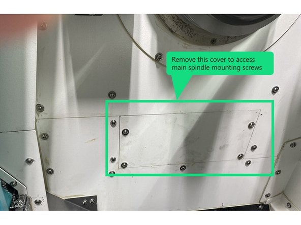
There are also 2 screws on the inside of the work area under the main spindle, remove the cover as shown in photo 2 to access those screws.
-
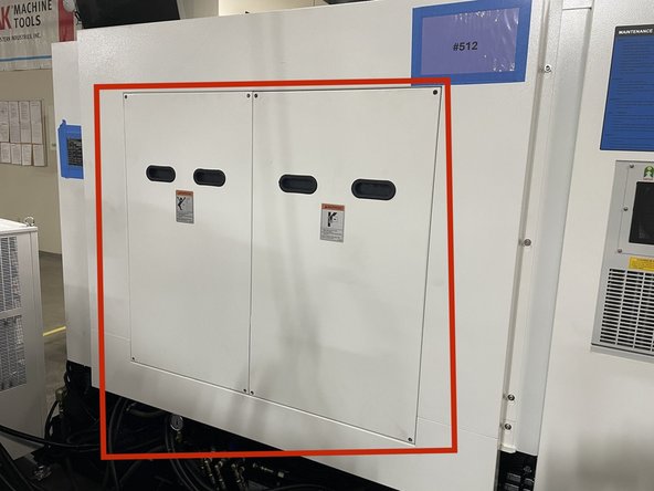
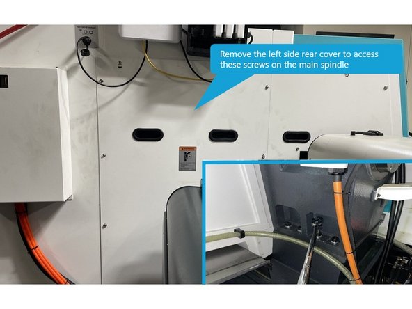
To access the final four (4) spindle mounting screws, remove the left side rear cover as shown in photo 3.
-
-
-
To adjust the main spindle you need to loosen the screws attaching the spindle to the main casting. To do this you will need a long 1/2 drive ratchet and a stubby 14mm hex driver socket. Loosen all 10 screws and then retorque to 60 in-lbs (70 kgf.mm). Photos 1 and 2 show the screw locations.
-
-
-
Before aligning the Main Spindle set up a test bar on the Sub Spindle to see if the Sub Spindle Centerline is in alignment with the Turret. If it is you can use the Sub Spindle to align the Main Spindle to it. The next few steps will cover the Main spindle and spindle centerline alignment and adjustments.
-
Next you need to attach a test bar to the sub spindle. To do so you need to remove the chuck or collet chuck from the Sub Spindle and clean spindle face and taper. Check Sub Spindle face and taper for knicks or dings and remove with a fine stone same as on the main spindle.
-
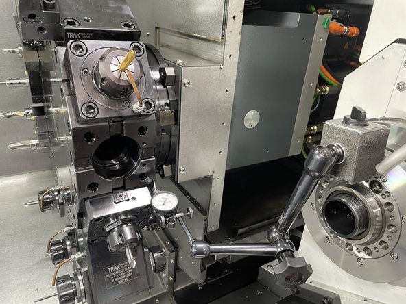
Once the Sub Spindle Test Bar is installed, install a dial indicator to the turret, and move the Z1 axis so that the indicator can measure the test bar closest to the Sub Spindle face. Set up the indicator to measure the spindle runout.
-
Now measure the test bar runout near the Sub Spindle face and adjust to 0.0001" or better (0.002mm). Use a plastic tipped hammer to tap test bar to achieve the desired runout. Torque the test bar mounting screws to 86 in-lbs (100 kgf.cm) and then again to 177in-lbs (200 kgf.cm) . Check runout to verify it didn't change when torqued.
-
-
-
Next check the alignment of the Sub Spindle. Set the indicator to measure the horizontal accuracy (side of test bar). Zero the indicator closest to the spindle face and move the Z1 Axis (turret) to the end of the bar. This should measure no more than 0.0004" (0.01mm).
-
Next set up the indicator to measure the top of the Test Bar and make the same measurement as above. It should not measure any more than 0.0004" (0.01mm). See Photo
-
The free end of the Sub Spindle Alignment Bar when measuring the vertical accuracy must be higher than the mounting end.
-
If the sub spindle is within spec you are going to zero on the horizontal "C" position of that spindle and align the main spindle to it.
-
-
-
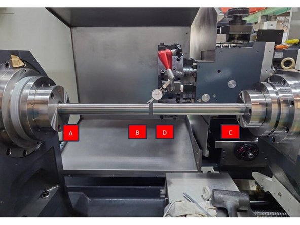
To set up to measure the Main and sub spindle Horizontal and vertical accuracy, move the test bar in the sub spindle to about 0.500" from the test bar in the main spindle.
-
Set up the indicator to measure the Horizontal Accuracy (side of the test bar). Start at position "C" and zero the indictor, move across the points "D", "B", and "A", the total error should be no greater than 0.0004" (0.01mm).
-
Now set up the indicator to measure the Vertical Accuracy (top of the test bar). Start at "C" and zero the indictor, move across the points "D", "B", and "A", again the total error should be no greater than 0.0004" (0.01mm).
-
Since the Main spindle horizontal accuracy measured greater than 0.0004" (0.01mm) in step 4, and Points "C" to "D" in the above point measured 0.0004" (0.01mm) or less, Zero the indicator at point "C" you are going to adjust the Main spindle points "A" and "B" to be within 0.0004" (0.01mm) or less than that of point "C".
-
The next step covers how to adjust the Main Spindle Horizontal Accuracy.
-
-
-
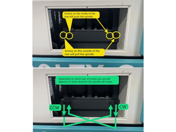
To align the Main Spindle Horizontal Accuracy there are 4 screws in the base casting, two screws to push the spindle and 2 screws to pull it.
-
The two screws on the base casting, depicted by the circles in the center of the row, will push the Spindle, while the two screws depicted by the circles on the outside of the row will pull the Spindle. This motion will cause the Spindle to rotate so it can be aligned. See Photo 1
-
Depending on whether the spindle requires a counterclockwise or clockwise adjustment, choose a pair of screws to tighten or loosen until the Main Spindle is in alignment with the Sub-Spindle. See Photo 1
-
Photo 2 shows the measurement points on both the Main and Sub Spindle alignment bars.
-
Zero the indicator on point "C" of the Sub Spindle test bar. Measure points "A" and "B" on the main spindle test bar and, using a pair of screws adjust the main spindle to where points "A" and "B" are within 0.0004" (0.01mm) of point "C". Tighten or loosen the adjustment screws in small increments to realign the main spindle with the sub spindle.
-
If the Main and Sub-Spindles are both out of alignment, zero the indicator at the "A" location of the Main Spindle and align the "B" location to within .0004" (0.01mm) of it.
-
This adjustment process may take several tries before achieving the correct alignment.
-
-
-
Once the horizontal accuracy is back in alignment retorque the mounting screws to 195 ft-lbs (2700 kgf.cm) Recheck the horizontal accuracy to verify it didn't change when the spindle mounting screws were torqued.
-
-
-
In the event the main spindle alignment was knocked out of spec due to a crash you should verify the turret alignment and spindle to turret centerline concentricity as well. The below link is used to measure and realign the turret assembly.
-
-
In the event that the Sub-Spindle was found to be out of alignment when realigning the Main Spindle you will need to realign it to the main spindle. The following Link is used to measure and realign the Sub-Spindle.
-
-
-
-
Once the Main spindle has been aligned with the Sub Spindle and you have verified or realigned the turret, you need to verify the Turret reference location with the Main and Sub Spindle centerline. The next few points will cover how to do that.
-
Clean the 5C Collet Chuck with WD-40 or an equivalent, and use a fine grit deburring stone to check for dinks or high spots on the mounting and measuring faces.
-
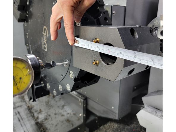
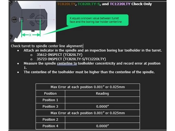
Attach an inspected Boring Bar Tool Holder to the Turret, the offset between the turret face and center of the bore must be known. Install the 5C collet chuck onto the Main Spindle face. Using a high accuracy 5C Collet install a Co-Axial dial indicator, so it is centered on the Spindle rotary axis.
-
Position the indicator so it is measuring on the ID of the boring bar holder and adjust the axis so the turret is close to the centerline of the spindle. The X-Axis should be at the value equal to the offset between the turret face and the center of the bore on the Boring Bar Holder. The Y-Axis should be positioned on 0.
-
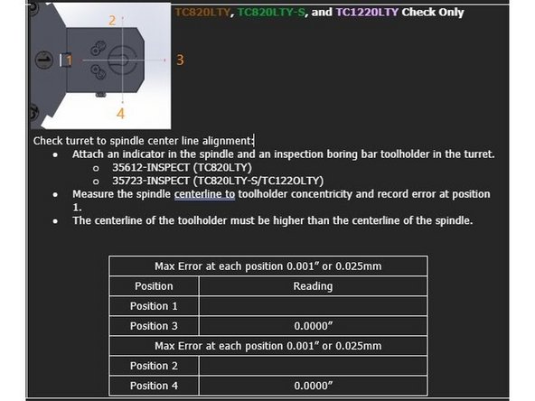
Starting with the C0-Axial indicator set to Zero at position 3, rotate the spindle 360° and record the indicator movement at positions 1, 2, and 4.
-
The maximum permitted error is 0.001" [0.025mm]. The centerline of the toolholder in the Y Axis must be higher than the centerline of the spindle.
-
Repeat check at turret position 7.
-
-
-
To align the turret centerline with the main spindle move the X and Y axis positions until the centerline of the tool holder bore is within spec of the spindle centerline, 0.001" (0.025mm) or less.
-
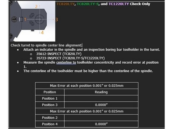
Starting with the digital indicator set to Zero at position 3, rotate the spindle 360° and record the indicator movement at positions 1, 2, and 4.
-
The maximum permitted error is 0.001" [0.025mm]. The centerline of the toolholder in the Y Axis must be higher than the centerline of the spindle.
-
Verify parameter settings MD 34100[0]:
-
X-Axis MD 34100[0]: Set to the value between the turret mounting face and the centerline of the tool holder bore. In this case it is 100mm as shown in photos 2 and 3.
-
Y-Axis MD 34100[0]: Set to 0.
-
Change parameter setting MD 34210[0] to 1 for the X and Y Axis. Press Jog -> Ref Point on the MCP and set the Feed Override to 0%.
-
Press and hold the "X" and "+" buttons on the MCP to reset the X-Axis position. Press and Hold the "Y" and "+" buttons on the MCP to reset the Y-Axis position.
-
-
-
Once all of the Main Spindle, Sub Spindle, and Turret alignments have been completed you can reinstall all of the outer covers back onto the machine. See Photos 1 thru 3.
-


![The maximum permitted error is 0.001" [0.025mm]. The centerline of the toolholder in the Y Axis must be higher than the centerline of the spindle.](https://d3t0tbmlie281e.cloudfront.net/igi/trakmtsupport/GaDXytRNQbCJkajy.medium)