Tools
Parts
No parts specified.
-
-
Before you can get started with the Sub Spindle alignment you must be sure the machine is level. If the machine is not level it's bed can become twisted and this can move the machine centers out of alignment. This can make the machine appear to be out of alignment when the machine is actually out of level. Use the below link to level the machine.
-
Link to level the machine: TRAK TC820si & TRAK TC820LTYsi - Leveling
-
-
-
Before getting started first verify that the Sub Spindle needs to be realigned.
-
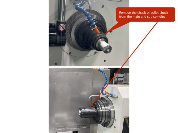
To check the alignment of the Main and Sub Spindle you first need to remove the chuck or collet chuck from both Spindles. Once removed close both Chucks. The test bars must not be up against the threaded Draw Tube of the Hydraulic Chuck assembly. It must be against the spindle face.
-
Before you can install the test bars you will need to remove the alignment pins from the main and sub spindle face.
-
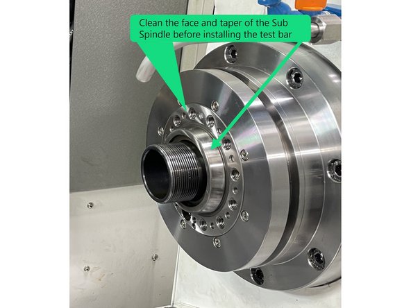
Clean the face and taper of the Main and Sub Spindle to remove any grease, coolant or other debris. Check for knicks or dings and remove using a fine stone (1000 or 1500 grit). Then wipe clean with a soft cloth to remove anything that may remain.
-
Clean your test bars and check them for any knicks or dings and stone if needed. Wipe clean before installing them onto the Main and Sub Spindle faces.
-
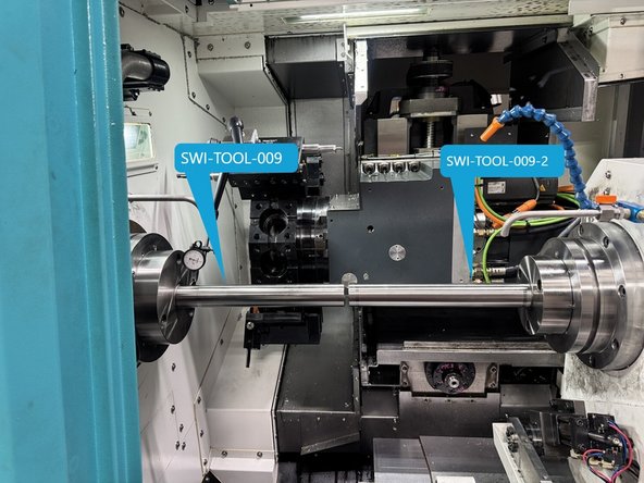
Install the test bar (SWI-TOOL-009) to the main Spindle and (SWI-TOOL-009-2) to the Sub Spindle and snug the mounting screws.
-
To align the Sub Spindle to the main Spindle you need test bars on both spindles because you are going to align the sub spindle centerline to the main spindle centerline.
-
-
-
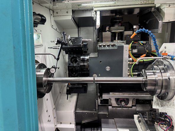
Install a dial indicator to the turret and move the Z1 axis so that the indicator can measure the test bar closest to the Main Spindle face. Set up the indicator to measure the spindle runout.
-
To align the test bar, use a plastic tipped hammer while rotating the Main Spindle and tap the test bar to the desired runout of 0.0001" (0.002mm) or better. Torque the test bar mounting screws to 86in-lbs (100 kgf.cm) and then again to 177in-lbs (200 kgf.cm) . Check runout to verify it didn't change when torqued. Do the same for the Sub Spindle.
-
-
-
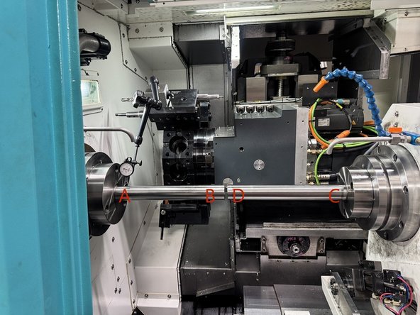
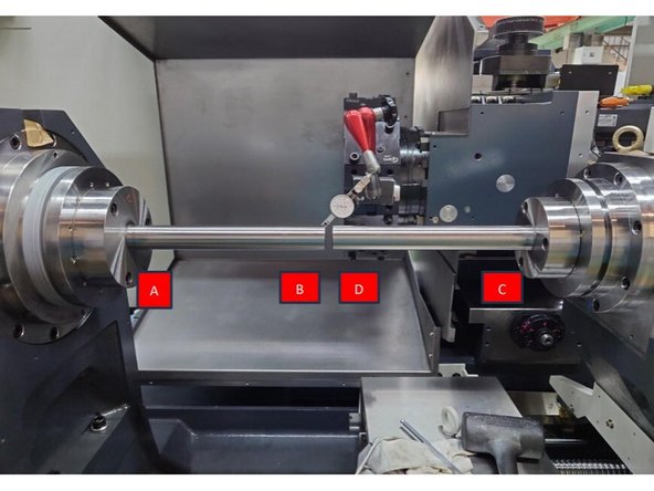
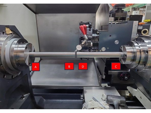
Set the indicator to measure the horizontal accuracy (side of test bar). Zero the indicator closest to the Main spindle face at Position A and move the Z1 Axis (turret) to positions B, D and C to measure the horizontal accuracy. This should measure no more than 0.0006" (0.015mm).
-
Next set up the indicator to measure the vertical accuracy (top of test bar) and make the same measurement as above. Again it should not measure any more than 0.0006" (0.015mm). See Photo
-
Note: The measurements from point A to Point B should be no more than 0.0004" (0.01mm). If points A to B are above 0.0004" (0.01mm) The Main Spindle needs to be aligned before you can align the Sub Spindle. The following Link is for the Main Spindle alignment procedure.
-
-
If either of the measurements are above 0.0006" (0.015mm) the Sub Spindle needs to be adjusted. The following steps will show you how to align the Sub Spindle.
-
-
-
To do the alignment of the TC820LTY-S Sub Spindle a few covers need to be removed. The next few points will show which covers need to be removed.
-
To remove the covers on the sub spindle you will need to remove the test bar from the Sub Spindle.
-
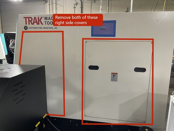
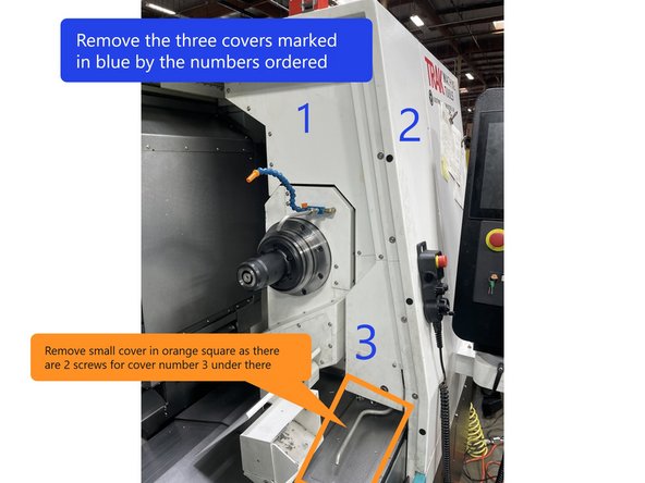
First remove the 2 right side covers as shown in Photo 1.
-
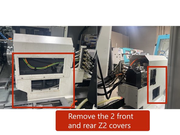
Next remove the Covers from around the Z2 Spindle assembly and from the front of the machine. Shown in Photo 2.
-
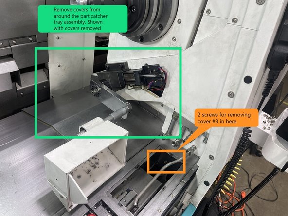
Remove the small stainless steel rectangular cover indicated by orange in photo 2 as there are 2 screws that mount cover 3 in there.
-
Remove the covers from around the part catch tray assembly as shown in Photo 3.
-
-
-
Remove the covers marked in red in photo 1 on each side of the Z2 Spindle assembly.
-
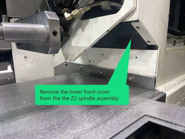
Remove the lower front cover of the Z2 Spindle assembly as shown in photo 2.
-
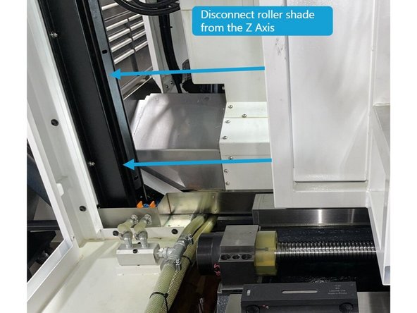
Disconnect the roller shade from the Z1 Axis as shown in Photo 3.
-
-
-
If it is determined that the Sub-Spindle needs a vertical alignment there are a few more covers that need to be removed. The next few steps will show you which ones. If the vertical accuracy doesn't need adjustment skip this step.
-
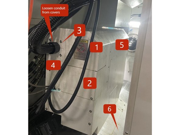
Remove covers 1 and 2, loosen the conduit then remove covers3 thru 6. See Photo 1
-
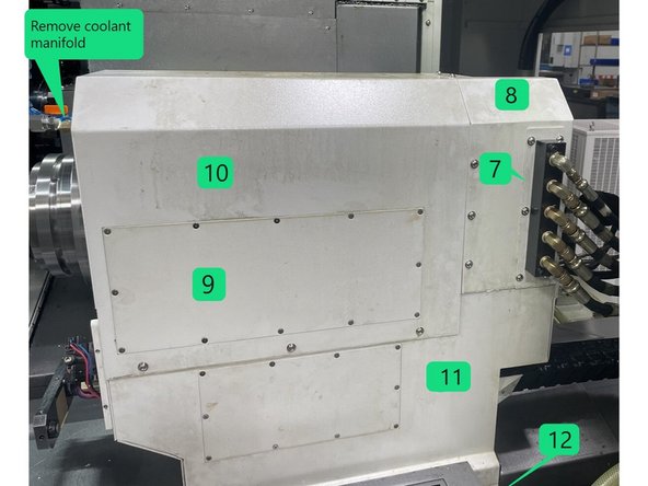
Next remove covers 7, 8, and 9 and remove the coolant manifold routed through cover 10, then remove covers 10 thru 12.
-
-
-
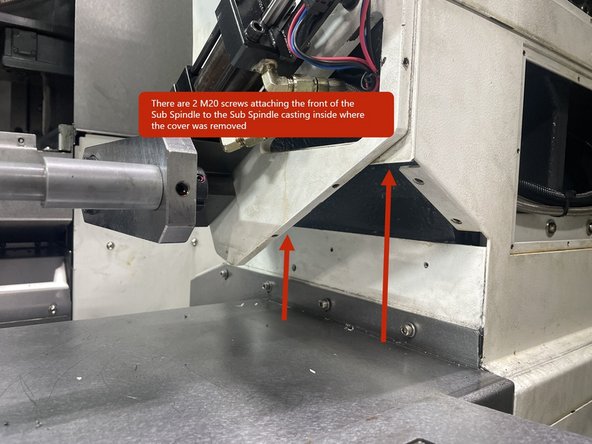
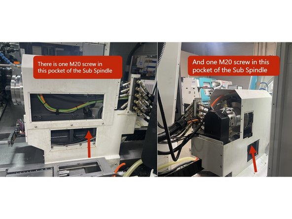
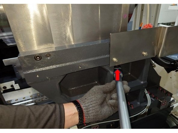
To adjust the Sub Spindle horizontal accuracy you need to loosen the (4) M20 screws attaching the spindle to the sub spindle casting. To do this you will need a long 1/2 drive ratchet and a stubby 17mm hex bit socket.
-
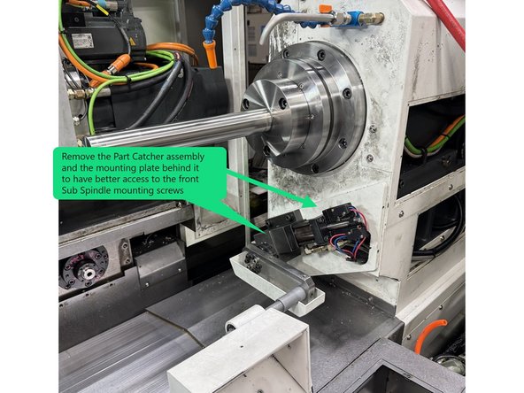
To have better access to the front 2 screws remove the part catch tray assembly and it's mounting plate.
-
Loosen the screws and then retorque to 60 in-lbs (70 kgf.mm). See Photos below for screw locations.
-
You may need to use a cheater bar on your ratchet to loosen these screws as they are torqued to 275ft-lbs of torque.
-
-
-
Reinstall and realign the test bar into the Sub Spindle.
-
To set up to measure the Main and sub spindle Horizontal and vertical accuracy, move the test bar in the sub spindle to about 0.500" from the test bar in the main spindle.
-
Set up the indicator to measure the Horizontal Accuracy (side of the test bar). Start at "A" and zero the indictor, move across the points "B", "D", and "C", the total error should be no greater than 0.0006" (0.015mm).
-
Now set up the indicator to measure the Vertical Accuracy (top of the test bar). Start at "A" and zero the indictor, move across the points "B", "D", and "C", again the total error should be no greater than 0.0006" (0.015mm).
-
If the vertical accuracy is out of spec, this needs to be adjusted first as this adjustment can cause changes to the horizontal accuracy. Depending how far the horizontal and vertical accuracies are out you may need to go back and forth between the two adjustments to get the horizontal and vertical accuracies in spec.
-
-
-
If the vertical accuracy of the sub spindle is out of spec it is likely that the lower casting has shifted on the linear guide bearing blocks due to a crash. The next few points show how to realign the casting to the bearing blocks.
-
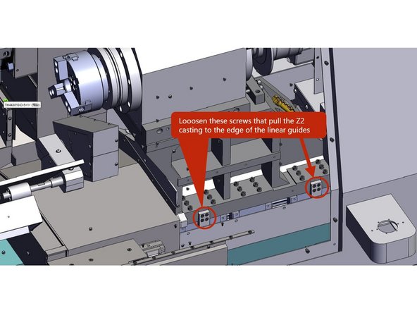
First loosen the screws that pull the casting to the reference side of the bearing blocks of the linear guides.
-
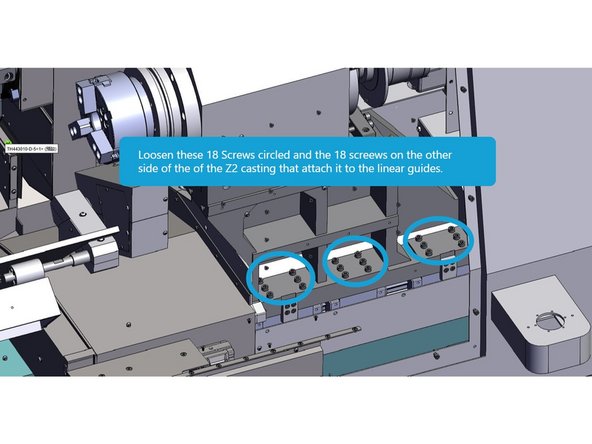
Then loosen the 36 screws that attach the lower Z2 casting to the bearing blocks on the linear guides.
-
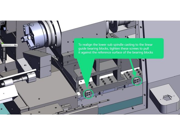
Once all of the screws are loose and the casting has relaxed itself on the linear guides, tighten the screws on the blocks that bring the sub spindle casting up against the reference side of the linear guide bearing blocks.
-
Then retighten the 36 screws that attach the sub spindle casting to the linear guides. Torque the screws to 28 ft-lbs. Recheck the Vertical Alignment, it should be no more than 0.0006" (0.015mm) from point "C" to "D" on the test bar.
-
-
-
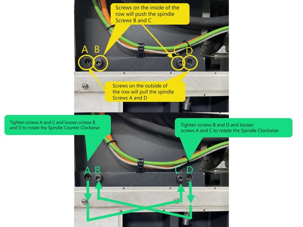
To align the Sub Spindle Horizontal Accuracy there are 4 screws in the base casting, two screws to push the spindle and 2 screws to pull it.
-
The two screws on the base casting, depicted by the circles in the center of the row, will push the Spindle, while the two screws depicted by the circles on the outside of the row will pull the Spindle. This motion will cause the Spindle to rotate so it can be aligned.
-
Depending on whether the spindle requires a counterclockwise or clockwise adjustment, choose a pair of screws to tighten or loosen to adjust the headstock. To rotate the Main Spindle counter clockwise tighten screws A and C and loosen screws B and D, For a clockwise adjustment tighten screws B and D and loosen screws A and C. See Photo 1
-
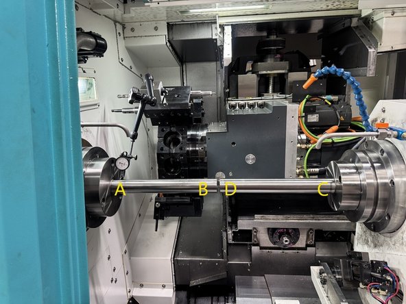
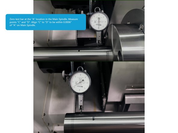
Photo 2 shows the measurement points on both the Main and Sub Spindle alignment bars.
-
Zero the indicator on point "A" of the Main Spindle test bar. Measure points "C" to "D" on the Sub Spindle test bar, using a pair of screws adjust the sub spindle to where points "C" and "D" are within 0.0006" (0.015mm) of point "A". Tighten or loosen the adjustment screws in small increments to realign the sub spindle with the main spindle.
-
Once the horizontal alignment has been completed go back and recheck the vertical alignment. If the vertical alignment has changed go back to step 10 and realign the vertical accuracy. Then verify that the horizontal accuracy didn't change. Both Horizontal and vertical accuracies should be with in 0.0006" of point "A".
-
This adjustment process may take several tries before achieving the correct alignment in both the horizontal and vertical accuracies.
-
-
-
Once the Horizontal and Vertical accuracy of the Sub Spindle has been adjusted back into spec, torque the 4 M20 screws that attach the upper sub spindle casting to the lower casting to 275 ft-lbs (3800 Kgf.cm).
-
Recheck the Horizontal and vertical accuracy to verify that nothing changed when the mounting screws were torqued.
-
-
-
Once the sub spindle alignment has been completed and the spindle torqued, reinstall all of the covers to the Sub Spindle assembly in the reverse order that they were removed.
-
-
-
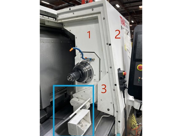
Reinstall covers 1, 2, and 3 in the reverse order they were removed.
-
Reinstall the parts catcher assembly covers depicted in the blue square.
-
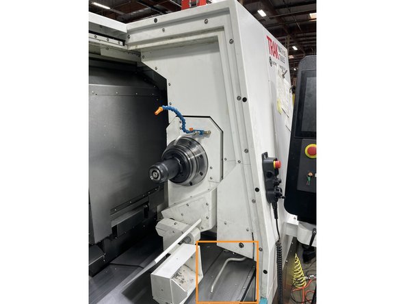
Reinstall lower sheet metal cover shown in the orange box.
-
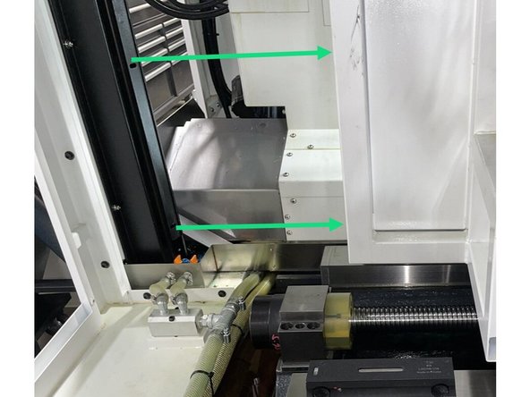
Reattach roller shade to Z1 Axis.
-
-
-
In the event the sub spindle alignment was knocked out of spec due to a crash you should verify the turret alignment and spindle to turret centerline concentricity as well. The link below is used to measure and realign the turret assembly.
-
-
-
-
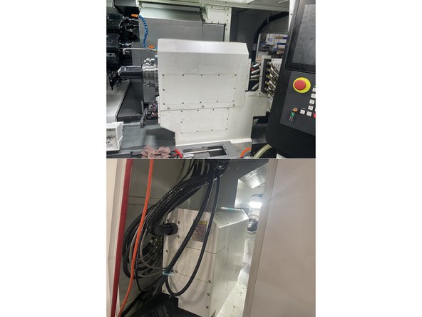
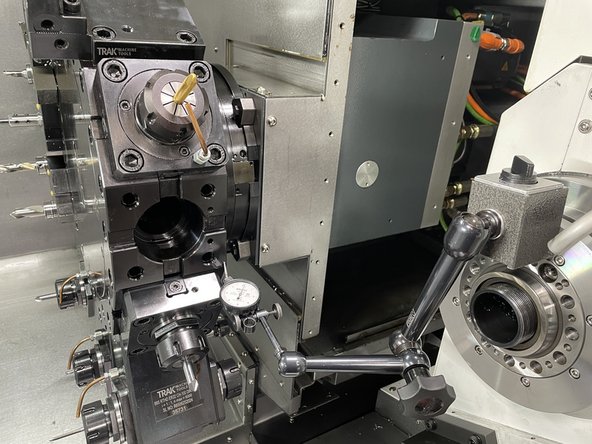
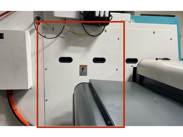
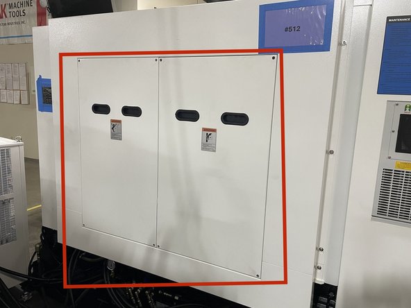
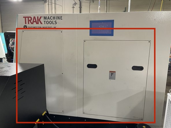
Once all of the Main Spindle, Sub Spindle, and Turret alignments have been completed you can reinstall all of the outer covers back onto the machine. See Photos 1 thru 3.
-

Team
