Parts
No parts specified.
-
-
The TC2 machines are shipped on a pallet with the leveling feet removed. The leveling feet must be installed before the machine is set on the floor.
-
Before installing the leveling feet in the machine base lubricate the threads of the levelers with Anti-Seize, light grease or oil. This will help the levelers thread smoothly through the casting. If the levelers don't thread smoothly you may need to chase the threads with an M16-2.0 Tap.
-
Install leveling feet into base and thread the levelers until they bottom out in the base of the machine, then set machine down onto the leveling feet. Verify there is at least 3.5" from the base of the machine to the floor so the pallet jack can fit underneath.
-
When leveling the machine you want it to be as low as possible and still be above 3.5" off of the floor to minimize vibrations during operation.
-
Verify that the machine can be powered up and if so power machine up at this time.
-
-
-
With the machine powered up, enable the servos and move the X Axis in the negative direction to the soft limit and then move the Z Axis in the negative direction to where the turret is over the chuck jaws. This puts the X and Z carriages near the center of the machine base.
-
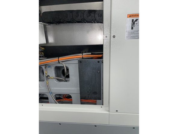
To put the levels in the correct locations to be able to level the machine you need to remove the upper rear cover to gain access.
-
-
-
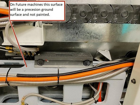
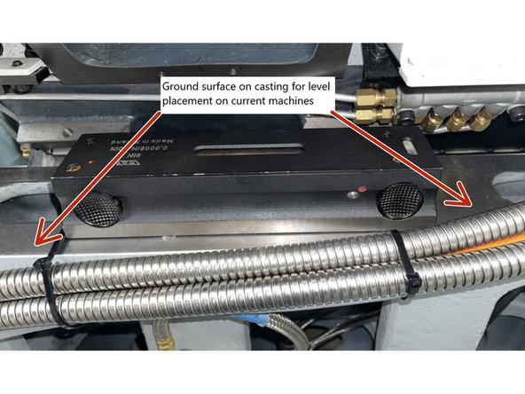
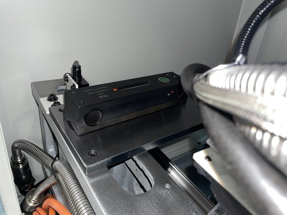
With the rear cover removed place the level on the machined surface of the casting that mounts the linear guides. This surface is used to level the machine in the Z or long Axis of the machine.
-
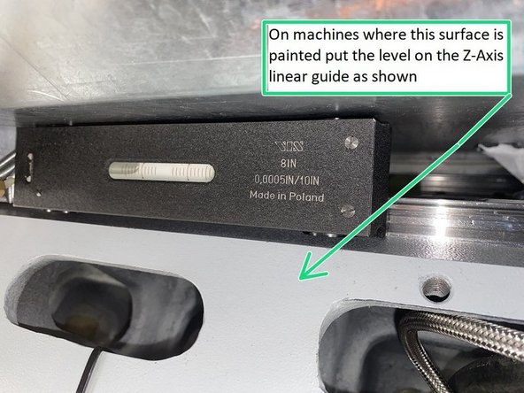
On early machines the surface for the level was a painted surface, so on those machines you should put the level on the Z Axis linear guide. See photo 3 for reference.
-
Photo 2 is showing the current machines with the top of the casting ground for the level placement.
-
Verify the machined surfaces are free from debris or burrs. Stone if needed.
-
Use either the left or right side front and rear leveling feet and adjust them until the bubble is centered. This will level the machine in the Z or long Axis of the machine.
-
The level is graduated in .0005"/10.0" per line and the spec for the level on the TC2 is .0005"/12.0"
-
When leveling the machine it is important to try to maintain equal pressure on all 4 of the leveling feet. This will prevent the machine from rocking if one of the feet is not touching the ground firmly.
-
-
-
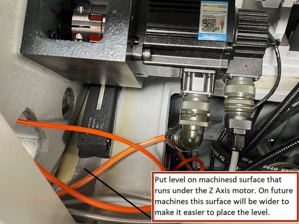
To level the machine in the X or short Axis one level is placed on the machined surface that runs under the Z Axis motor.
-
Verify the machined surfaces are free from debris or burrs. Stone if needed.
-
To place the second level we need to add a plate to the Z casting at the opposite end of the machine. This is to measure if there is any twist in the casting that we can adjust out with the leveling feet. See photo 2 for reference
-
The leveling plate is attached to the Z casting when not in use. See photo 3 for location
-
Do not try to move the Z Axis when the leveling plate is installed a collision may occur. Remove the leveling plate once machine is leveled and return it to it's storage location.
-
-
-
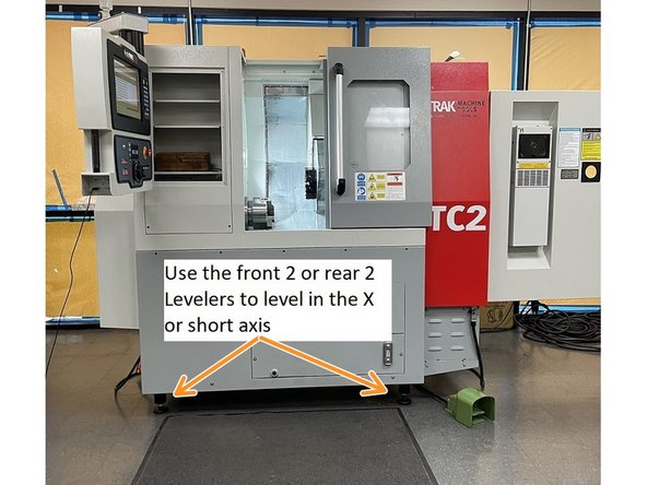
Using the 2 front or rear leveling feet, raise or lower the machine until the bubble is centered in the level. This will level the machine in the X or short axis of the machine. Again verify that there is fairly equal pressure on all 4 of the leveling feet.
-
You may need to go back and forth a few times between leveling the X and Z axis until the machine is level in both axis.
-
When leveling the machine you want it to be as low as possible and still be above 3.5" off of the floor to minimize vibrations during operation.
-
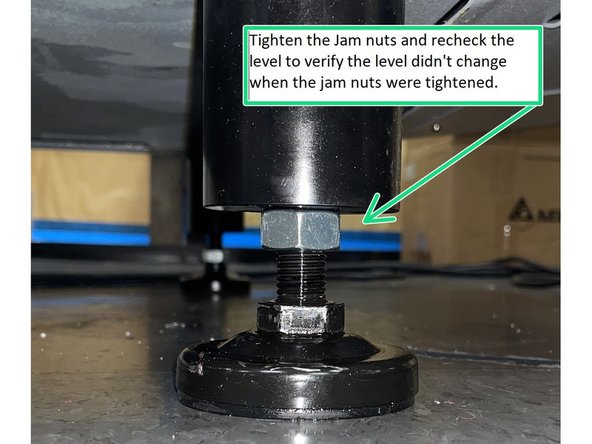
Once the machine is level tighten the jam nuts on the leveling feet to secure them from moving and recheck the level to make sure there was no change when the jam nuts were tightened.
-
The level is graduated in .0005"/10.0" per line and the spec for the level on the TC2 is .0005"/12.0"
-
Cancel: I did not complete this guide.
One other person completed this guide.


