
Introduction
This guide is designed to cover the change over from a 3 Jaw Hydraulic Chuck to the installation of the 5C Collet Chuck and back. The procedure begins with the removal of the 3 Jaw Hydraulic Chuck, then moves on to the installation of the 5C Collet Chuck then back to the installation of the 3 Jaw Hydraulic Chuck, and finally the adjustment of the Chuck Clamp /Unclamp Sensors.
-
-
Use the foot pedal to move draw tube to the fully retracted position. Hold one of the jaws with a crescent wrench and loosen the screws on the jaws and remove two of the jaws.
-
Hold the remaining jaw with the crescent wrench and loosen the six screws that are holding the chuck to the spindle
-
Leave one or two screws in the chuck loosely to prevent the chuck from falling when it comes loose from the draw tube when removing the chuck in the next step.
-
Remove the remaining jaw from the chuck.
-
-
-
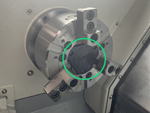
Remove the chip cover from the center of the chuck
-
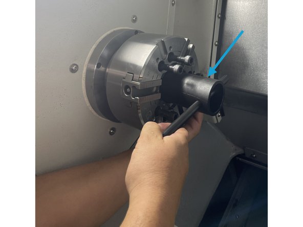
Move the draw tube to the fully extended (open) position. Install the draw nut tool, and unscrew the chuck from the draw tube.
-
Once the chuck is free from the draw bar remove the one or two screws that were left in the chuck and remove the chuck from the machine.
-
Once the chuck is removed from the spindle reinstall the center cap and jaws to the chuck and bag the hardware and keep with the chuck for use when reinstalling the 3 Jaw Hydraulic Chuck.Take note the jaws are numbered and so is the chuck. When reassembling the chuck be sure to put the jaws in the locations that correspond to the numbers.
-
For 3 Jaw Hydraulic Chuck installation skip ahead to step 6 for instructions.
-
-
-
This part of the procedure starts with the chuck removed. For chuck removal procedure see steps 1 and 2.
-
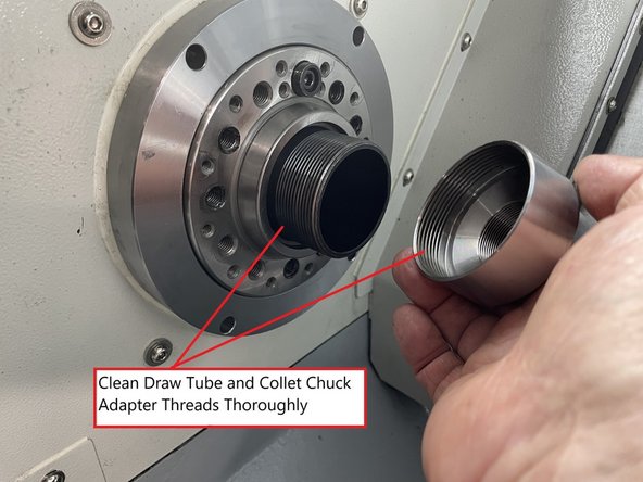
To install the collet chuck clean the draw tube and collet chuck adapter threads thoroughly. Make sure the draw tube is in the fully extended position. Apply a light coat of lithium grease or anti-seize to the draw tube threads.
-
The adapter may be installed into the collet chuck when not in use to prevent it from getting lost, if so remove it from Collet Chuck before installing to draw tube.
-
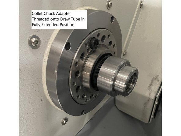
Fully thread the collet chuck adapter onto the draw tube then back out about 1/2 a turn.
-
Do not force adapter onto the draw tube it should thread easily. Forcing the adapter could damage the draw tube threads.
-
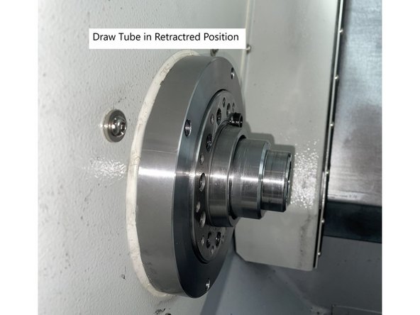
Retract the draw tube.
-
-
-
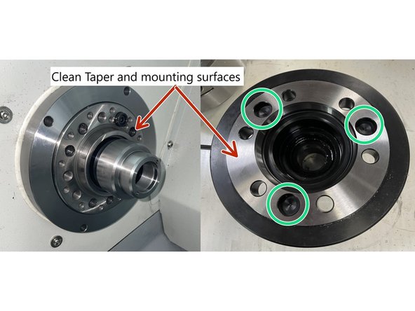
Clean the taper and mounting surface of the spindle and the inside taper and back mounting surfaces of the collet chuck.
-
Align one of the 3 alignment holes with the drive button on the spindle and push the collet chuck onto the chuck adapter on the draw tube.
-
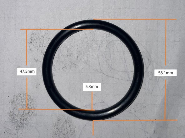
O-ring in collet chuck may have swollen over time. If you run into difficulty installing the chuck over the collet adapter, the o-ring may need to be replaced. A spare O-Ring comes with the collet chuck kit. O-Ring dimensions for replacement are in Photo 2.
-
Insert the six(6) M10 X 30 SHCS screws and torque to 53.5ft-lbs.
-
-
-
To install the collet move the draw tube to the fully extended position. Remove the drive key(silver M5 SHCS) and both of the M5 X 16 SHCS from the collet chuck.
-
The 5C collets have a keyway in them that corresponds with the drive key(Silver M5 SHCS) in the collet chuck. When the collet is installed and adjusted the collet is oriented so the tip of the drive key fits into the keyway. The drive key is then tightened to prevent the collet from coming loose during operation.
-
Take note of where the keyway on the collet is located. Use the collet tool to install the collet and thread into draw tube adapter until collet angle contacts angle in collet chuck. Continue to thread collet into draw tube adapter until the keyway in the collet lines up with one of the tapped holes in the collet chuck.
-
Collet tool comes from the manufacturer with the collet chuck kit.
-
Insert and tighten drive key in collet keyway. Insert and tighten the two(2) M5 X 16 SHCS into the collet chuck.
-
To verify the collet adjustment, clamp and unclamp the collet several times to verify the collet clamps tightly on the material when closed and that the material can be removed and reinserted when open.
-
You may need to remove the drive key and (2)M5 X 16 SHCS and tighten or loosen the collet 120 degrees to get proper collet adjustment. Reinsert drive key and both M5 SHCS when adjustment is complete.
-
Once the collet chuck has been installed and adjusted skip to step 8 to adjust the Clamp/Unclamp switches for the collet chuck.
-
-
-
To remove the 5C Collet chuck to install the 3 Jaw Chuck follow the Collet Chuck installation steps in reverse order.
-
Before installing the 3 Jaw Hydraulic chuck, clean the draw tube and chuck threads. Add a light coat of anti-seize to the chuck and draw tube threads.
-
3 Jaw Chuck installation Steps
-
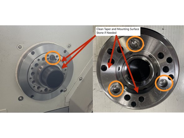
Clean the taper and mounting surface on the spindle and chuck, check for burrs or nicks, stone if needed.
-
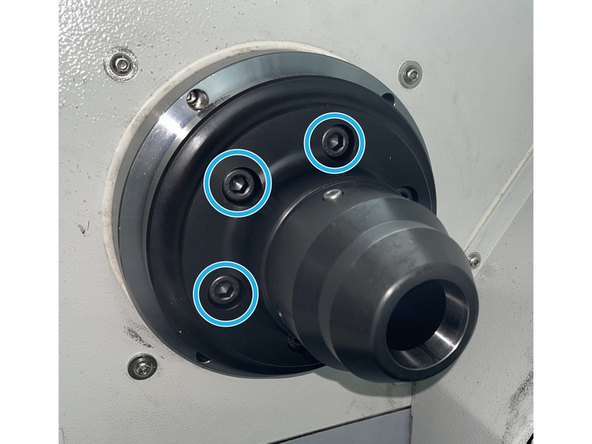
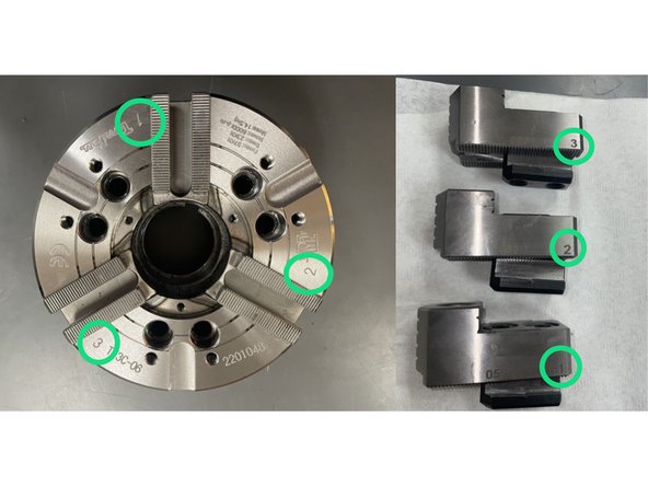
Take note the chuck has three(3) alignment holes for the drive dog. Anyone of them can be used when installing the chuck. See Photo 1
-
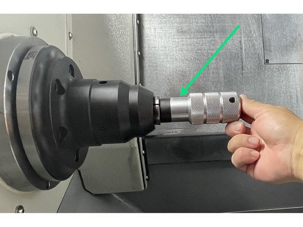
Retract the drawtube then install the chuck aligning it with the drive dog in the spindle. Using the chuck installation tool thread the chuck onto the drawtube until it stops (about 4 turns) then extend the drawtube all the way out and thread the chuck onto the drawtube until it stops again (about 5 more turns) then back it out about a half a turn.
-
Do not force the draw nut when removing or replacing the chuck. Forcing the draw nut can damage the drawtube threads. The draw nut should turn without binding.
-
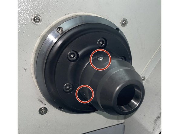
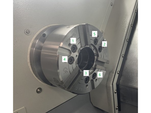
Install the six(6) M10-1.5X110 SHCS chuck mounting screws into the chuck . Following the pattern in photo 3 snug the screws for now.
-
-
-
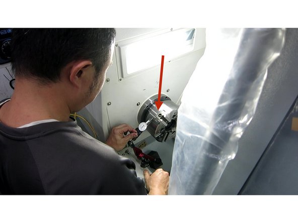
Set up a 0.0001" dial indicator on the chuck and measure the runout. The runout on the perimeter and face should be less than .0002" (5um). Tighten the six(6) mounting screws in a crossing pattern (same as in previous step) while watching the runout. Verify the runout stays in spec while tightening the screws. Torque to 58ft-lbs. See Photo 1
-
Reinstall one of the chuck jaws to hold the spindle while torquing the chuck to 58ft-lbs.
-
Reinstall the center cap and other two chuck jaws. The jaws and chuck are numbered, return the jaws to the corresponding location on the chuck. Torque the jaws to 47ft-lbs. See Photos 2 and 3
-
-
-
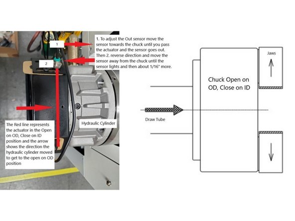
There are two sensors located on the coolant collector at the back of the spindle. These sensors are used to indicate the limits of the drawtube actuation. After changing the work clamping device the drawtube travel may have changed and the sensors may need realigning.
-
Before aligning the sensor actuation verify there is a 1mm gap between the sensor and the actuator inside the coolant collector.
-
To adjust the "Chuck Out" sensor actuate the Hydraulic Chuck cylinder to the Chuck Open on OD, Clamp on ID position. Next 1. move the sensor towards the chuck pass the actuator until the sensor goes out then 2. reverse direction away from the chuck until the sensor just lights up, then move about 1/16" more.
-
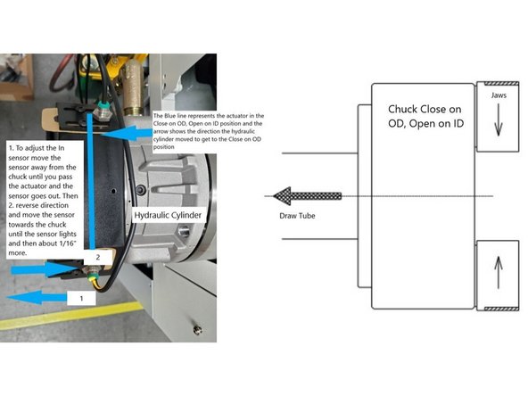
To adjust the "Chuck In" sensor actuate the Hydraulic Chuck cylinder to the Chuck Clamp on OD, Open on ID position. Next 1. move the sensor away from the chuck pass the actuator until the sensor goes out then 2. reverse direction towards the chuck until the sensor just lights up, then move about 1/16" more.
-
Actuate the Hydraulic Cylinder back and forth a few times to confirm the sensors are detecting the max travel of the Hydraulic Cylinder actuation. Then put a piece of material in the chuck and clamp on it and verify when the chuck is clamped on material that neither sensor is lit.
-
When the work holding device is clamping on the OD or ID of a workpiece neither sensor should be lit. The work holding device should be clamping the work piece near the center of the Hydraulic Cylinder travel.
-


Cancel: I did not complete this guide.
One other person completed this guide.