Introduction
With this guide you will be able to remove the standard manual chuck and install the hydraulic chuck option on the TC2 turning centers.This guide covers the installation of the mechanics, the electronics and the hydraulics. It also covers the alignment of the hydraulic cylinder and draw tube and the chuck. This guide is meant to be used in conjunction with Drawing P/N 35090 Hydraulic Chuck TC2
-
-
Remove the motor cover on the left side of the machine.
-
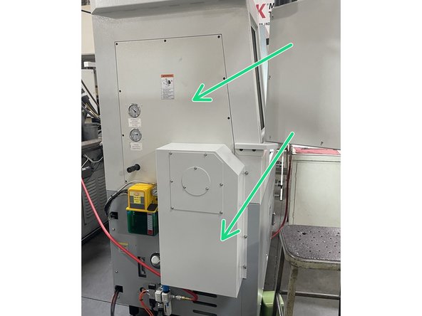
Remove the lube pump and the Air regulator/ solenoid assembly. Set the lube pump on a bucket or something tall enough to keep it from hanging on the oil line or electrical cable. Remove the upper and lower left side sheet metal covers. Once the lower cover has been removed you can remount the Lube pump to the casting.
-
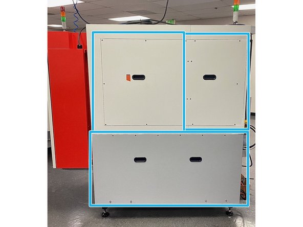
Remove both of the upper and the lower rear sheet metal covers.
-
-
-
Loosen the six(6) motor mounting screws and turn the motor adjustment screw clockwise to loosen the belt tension and remove the belts. Remove the spindle pulley cover plate.
-
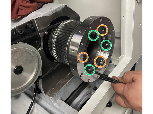
Remove the six(6) screws in the pulley. There are three(3) long screws and three(3) short ones.
-
Remove the pulley retaining ring from the spindle.
-
This hydraulic chuck installation also shows the spindle pulley and belts being changed to go from low speed to the high speed option.
-
If you are not adding the high speed option to this machine at this point, loosen the belts, remove the retaining ring but don't remove the belts or spindle pulley.
-
-
-
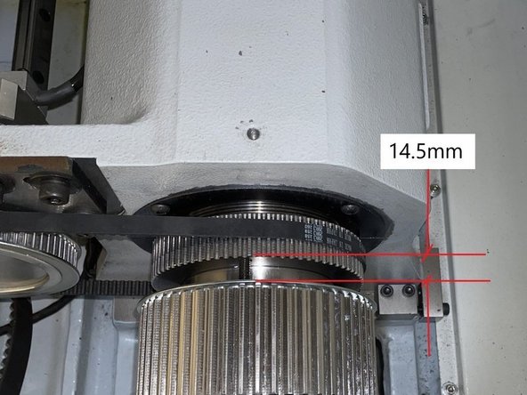
If you are not adding the high speed option adjust the existing pulley to 14.5mm between it and the encoder pulley and follow steps below.
-
Remove the low speed pulley and install the high speed pulley. Align it so that there is a 14.5mm gap between it and the encoder pulley.
-
Install the hydraulic chuck adapter ring.Tighten until it stops on high speed pulley and then loosen until you can install the three(3) long screws through the adapter and drive pulley and thread into the encoder pulley. Snug them for now, do not tighten.
-
Then install the three(3) short screws into the chuck adapter and torque to 156in-lbs. Install the new belts and Leave loose for now.
-
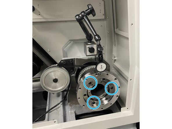
Set up a 0.0001" dial indicator and measure the runout of the face of the adapter. Tighten the three(3) longer(M6-1.0X120mm) screws slowly while rotating the spindle and watching the indicator. Adjust to 0.0002"(5um) max and tighten the screws to 156in-lbs while maintaining the runout below the 0.0002"(5um) spec.
-
-
-
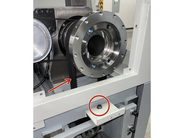
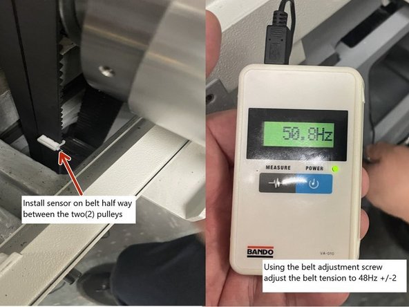
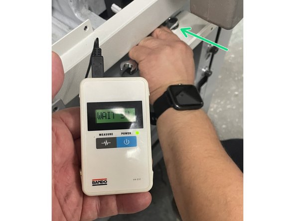
Install the belts and start adjusting the tension using the belt adjustment screw. Using the Bando belt tension meter install the sensor on the belt halfway between the two(2) pulleys. Turn meter on press measure and pluck the belt. It should be tensioned to 48Hz +/-2
-
If the belt needs to be adjusted tighten or loosen the adjustment screw until 48Hz +/-2 is achieved. Tighten the motor mounting bracket screws and check again to insure the tension didn't change when the screws were tightened.
-
Rotate the spindle by hand and make sure the encoder and spindle belts are tracking correctly.
-
-
-
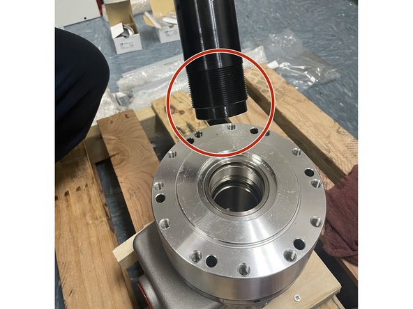
Clean the threads on both ends of the draw tube and inside of the hydraulic cylinder. Put a small amount of Vibra-Tight on the end of the draw tube with the shoulder, then install it into the hydraulic cylinder. See Photo 1. Tighten draw tube into cylinder with a chain or strap wrench
-
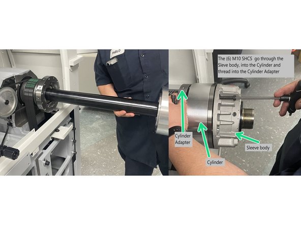
Once the draw tube is installed to the hydraulic cylinder, install the assembly into the spindle using six(6) M10-1.5X90 SHCS screws and snug them for now.
-
You will need to rotate the cylinder for the holes in the cylinder to line up with the holes in the sleeve and the adapter. Once the first 2 screws have been started you will need to rotate the cylinder and spindle to install the remaining (4) screws through the Sleeve body and into the cylinder.
-
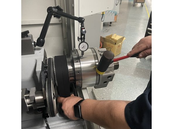
Set up a 0.0001" dial indicator and measure the runout of the cylinder. Tap with a plastic tipped hammer and adjust the runout to 0.0006"(15um) max. Torque the screws to 47 ft-lbs of torque. Recheck runout to be sure it didn't change when the screws were torqued.
-
If the runout exceeds 0.0006" after tightening to 47 ft-lbs, repeat the last step.
-
-
-
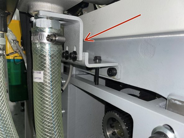
Install the anti-rotation bracket to the spindle motor belt tension bracket. Adjust the height of the anti-rotation bracket to allow the hydraulic cylinder to move side to side, the anti-rotation bracket must not be tight on the hydraulic cylinder otherwise it will fail. See Photo 1.
-
-
-
Before installing any of the electrical components or connecting any of the wires or cables shut the machine down and disconnect the main power for safety.
-
The TC2 electrical components come prewired and mounted to a piece of DIN rail. Before installing into the electrical cabinet check the wiring against drawing 35090 to verify everything is wired correctly.
-
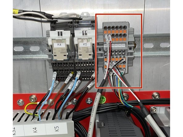
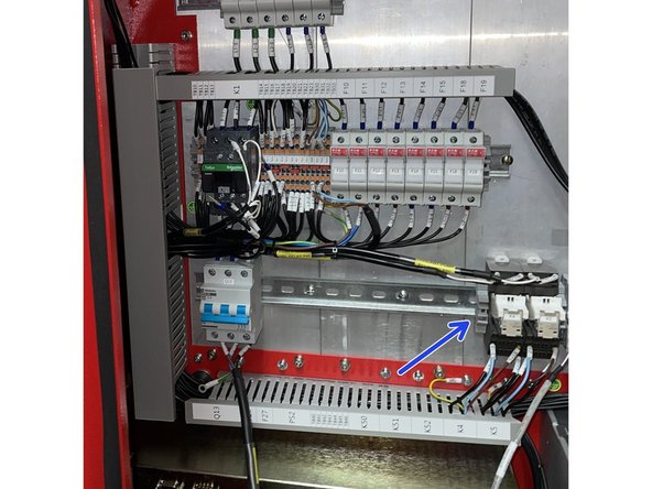
Remove terminal blocks TB60 to TB65 and install them and the end stop onto the DIN rail that has K4 and K5 installed to it and, install them to the right of the K5 relay end stop. See Photo 2
-
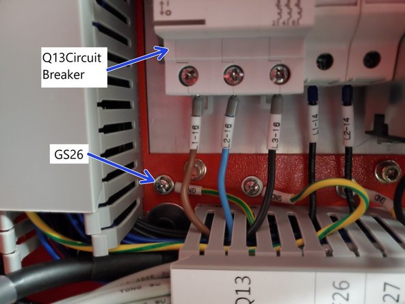
Next install Q13 onto the DIN rail in the electrical cabinet that K4 is mounted to and install it to the far left of the K4 relay. Connect the cable (29032-238), to the Q13 circuit breaker, L1-16 to Q13-T1, L2-16 to Q13-T2, L3-16 to Q13-T3, and then connect the ground wire to the ground screw GS26 in the electrical cabinet. See Photo 3.
-
-
-
Remove the end stop on the DIN rail next to the K4 relay. See Photo 1
-
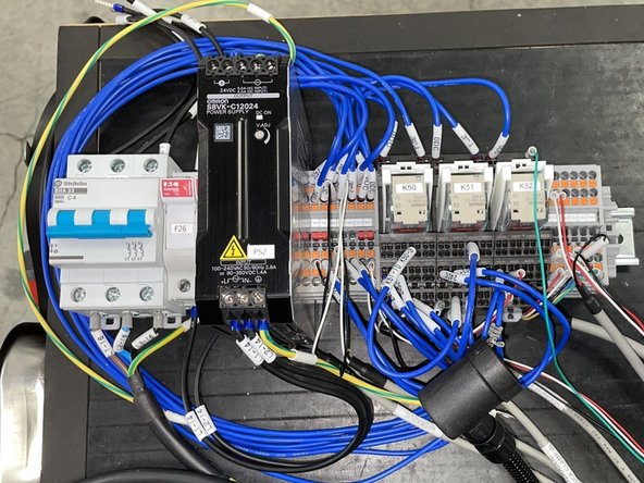
Now remove F26 and 27, PS2, TB40 to TB46 and K50, K51, K52 from the packaging DIN rail and attach F26 and 27 next to Q13 then attach PS2 next to F27, then TB40 to TB46 next to PS2 and finally attach K50, K51 and K52 between TB46 and K4. See Photo 2 for details.
-
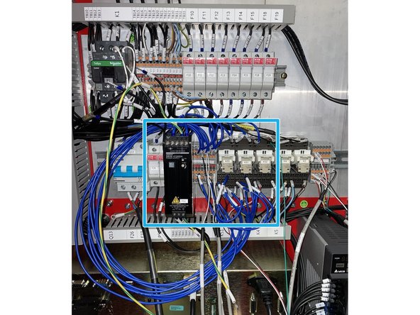
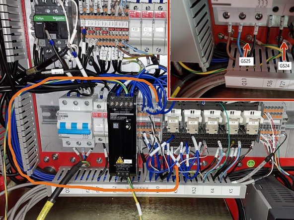
Route blue wires into wire ways as shown in Photo 3.
-
Next route the ground wire from the top of PS2 to ground screw GS25, then route the ground wire from the bottom of PS2 to ground screw GS24. See Inset in Photo 3
-
-
-
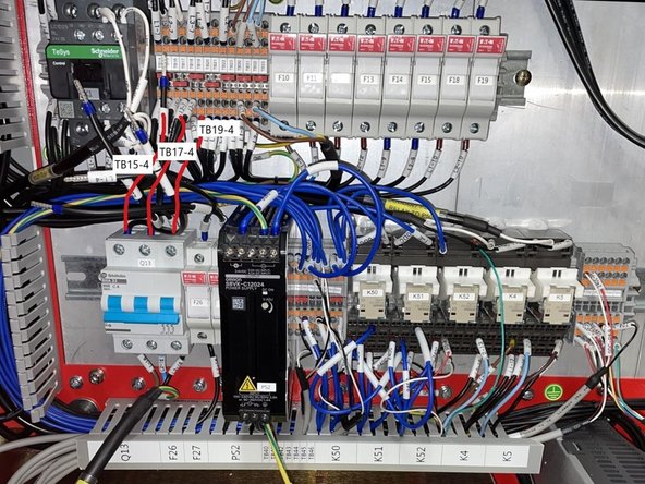
Connect wire L1-7 from Q13-L1 to TB15-4, Connect wire L2-7 from Q13-L2 to TB17-4 and connect wire L3-7 from Q13-L3 to TB19-4. See Photo 1
-
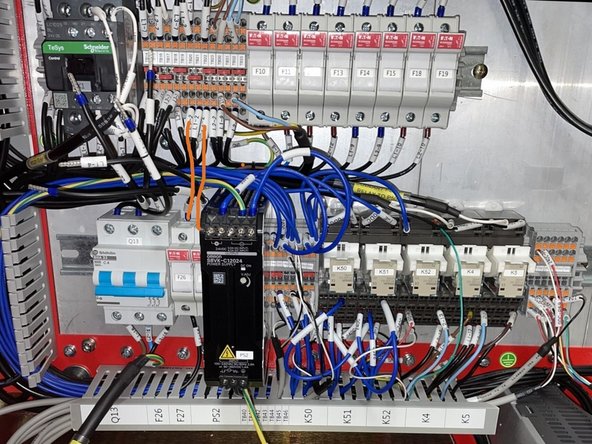
Connect wire L1-4 from F26-1 to TB20-3 and wire L2-4 from F27-1 to TB22-3. See Photo 2
-
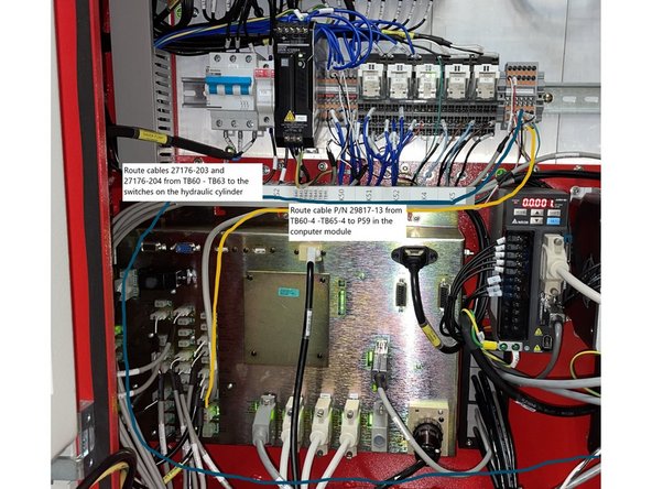
Connect the 6 pin connector on cable P/N 29817-13 from TB60-4 - TB65-4 to IN-P59 on the computer module. See Photo 3
-
Route the other 2 cables (P/N 27176-203 and 27176-204) from that terminal block through the cable track and down along the bottom of the cabinet. Leave here for now we will address the routing to the switches in a later step. See Photo 3
-
-
-
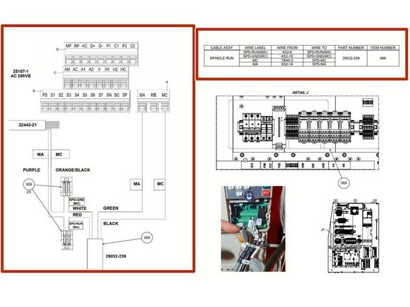
Locate cable 29032-239 and route it up to the AC Drive. Remove wires MC and MA from the AC Drive. Use drawing (35090) and wire chart in Photo 1 to connect cable 29032-239 to the AC Drive.
-
Locate cable P/N 27635-261 Chuck Pedal and attach the pedal connector end to the outside of the electrical cabinet. The connector mounts with M3 screws that are supplied with the connector. Route the other end of the cable to the computer module and connect to P48 on the computer module. See Photo 2
-
You may need to chase the M3 threads in the electrical cabinet that mount the foot pedal connector as they may be contaminated with paint
-
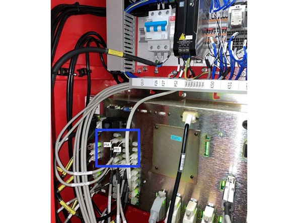
Locate cables "Hydraulic Chuck In P54" and "Hydraulic Chuck Out P55" (connected to TB42 - TB44) and route them through the wire way and down to the computer module and connect them to P54 and P55 on the computer module. See Photo 3
-
-
-
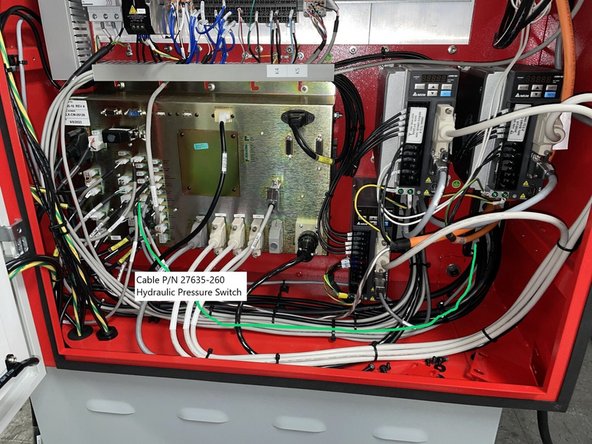
Locate cable P/N 27635-260 (Hydraulic Pressure Switch Cable) and connect to the computer module at IN-P29 and route down along the floor to the right rear corner of the cabinet. See Photo 1
-
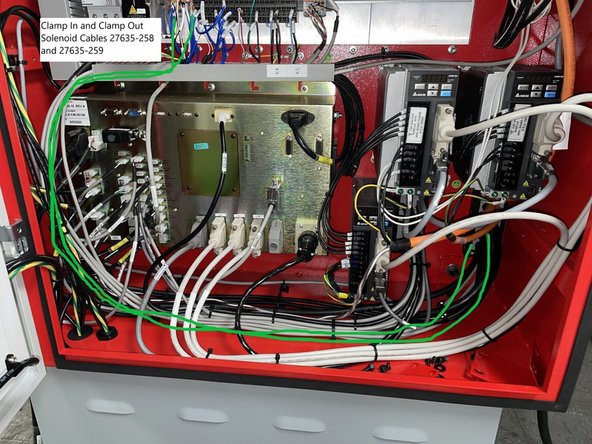
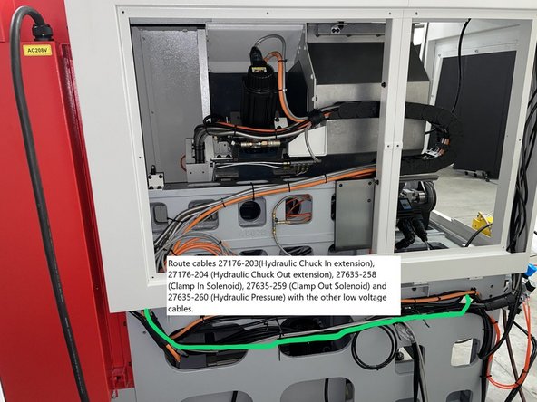
Route cables 27635-258 (Clamp In Solenoid) and 27635-259 (Clamp Out Solenoid) through the wire way above the computer module and down along the side of the cabinet and along the floor to the right rear corner of the cabinet. See Photo 2
-
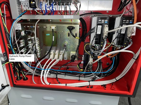
Route the Hydraulic pump power cable (29032-238) from Q13 down and along the floor with the other high power cables to the right rear corner of the cabinet. See Photo 3.
-
-
-
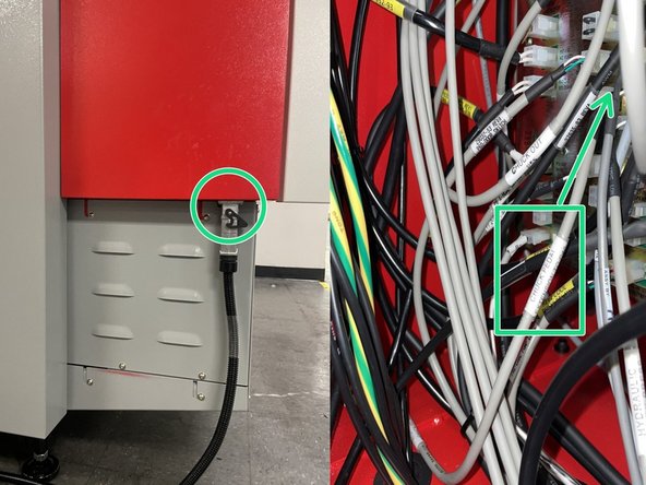
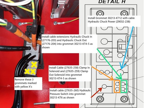
Remove the screws that hold the grommet adapter plate in place and remove the 3 grommets marked with Yellow X's in Photo 1. Next install cable 27635-260 into grommet 30213-KT6 and put into the grommet adapter plate as shown in Photo 1. (red arrow)
-
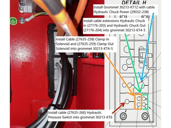
Install 4 cables into grommet 30213 -KT4-5 such that the thinner cables go in first (27635-258 Clamp In Solenoid and 27635-259 Clamp Out Solenoid) then the thicker cables (27176-203 Hydraulic Chuck In Extension and 27176-204 Hydraulic Chuck Out Extension).
-
Next install cable 29032-238 (Hydraulic Chuck Pump Power) Cable into grommet 30213-KT12 and install Grommet into the grommet adapter plate as shown in Photo 1. (blue arrow) Finally route the cables through the cabinet and reinstall grommet adapter plate and grommets into the electrical cabinet.
-
From machines #9 and forward the cables exit the electrical cabinet near the corner of the cabinet as depicted in Photo 2.
-
-
-
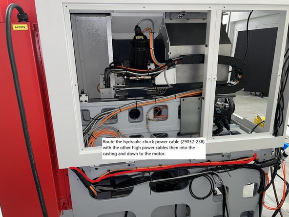
Route the Hydraulic Pump Power cable with the Spindle Motor Power cable along the outside of the casting and follow it into the casting to where the hydraulic pump motor will be installed.
-
Next route the Hydraulic chuck in and out cables (27176-203 and 27176-204), the clamp in and clamp out solenoid cables (27635-258 and 27635-259) and the pressure switch cable (27635-260) along the side of the casting with the other low voltage cables and leave outside of the casting for now.
-
-
-
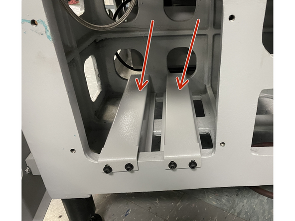
Install the Hydraulic tank support brackets to the base casting.
-
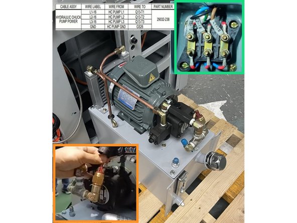
Using a pallet jack raise the hydraulic tank assembly up high enough that it can be moved into the base casting. Before moving the tank assembly all the way in connect the pump power cable to the pump motor. Wire L1-16 to HC Pump L1, L2-16 to HC Pump L2, L3-16 to HC Pump L3 and the ground to pump ground. See Photo 2.
-
Feed the Hydraulic Pressure switch cable (27635-260) from outside the casting into the casting and attach to the pressure switch, refer to drawing 35090 for wiring info. See Photo 2
-
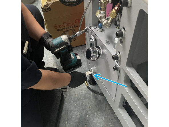
Once the motor power and pressure switch are connected move the assembly into place and install the four(4) screws that attach it to the base casting. You may need to use a pry bar to get the screw holes to line up so you can get them started.
-
-
-
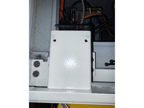
Locate the clamp/ unclamp solenoid mounting bracket (35092-3) and install it to the casting.
-
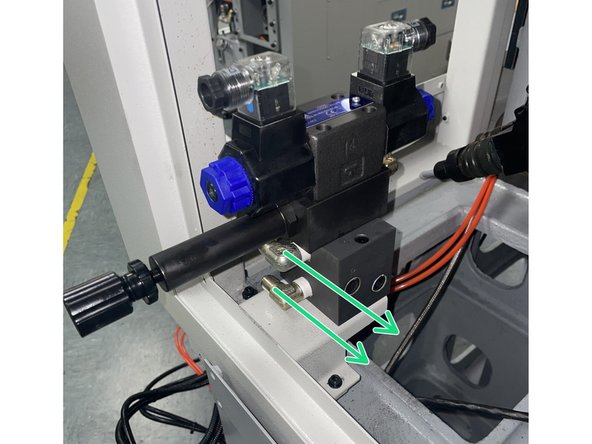
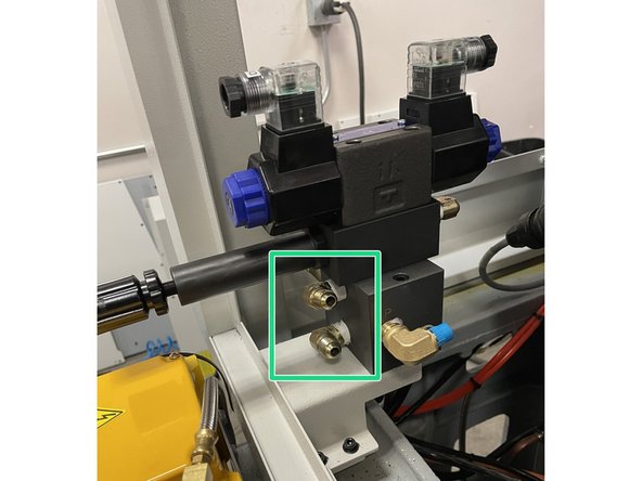
Next mount the solenoid assembly to the mounting bracket and tighten the two (2) 90 degree fittings 180 degrees to point towards the hydraulic cylinder. See Photos 2 and 3
-
If you can't tighten the fittings 180 degrees remove them and re-apply teflon tape and tighten to where they point towards the hydraulic cylinder.
-
-
-
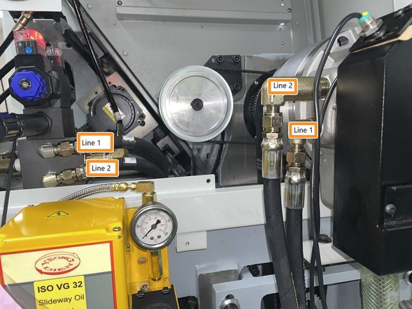
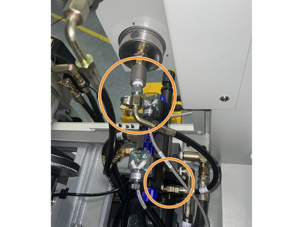
Attach hydraulic lines one(1) and two(2) from the solenoid valve to the hydraulic cylinder as shown in photo 1.
-
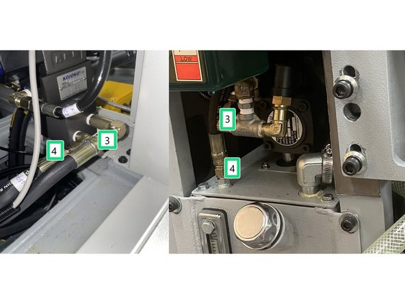
Attach lines three(3) and four(4) from the solenoid valve to the pump and tank as shown in photo 2.
-
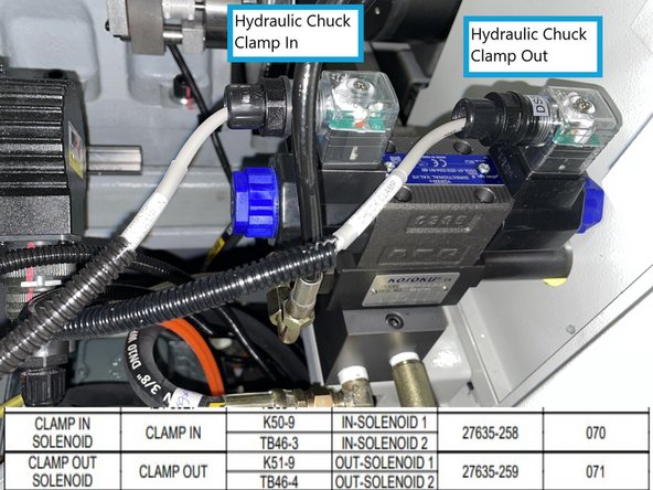
Connect the Hydraulic Chuck Clamp In and Hydraulic Chuck Clamp Out cables to the solenoid. Reference photo 3 for wiring information.
-
-
-
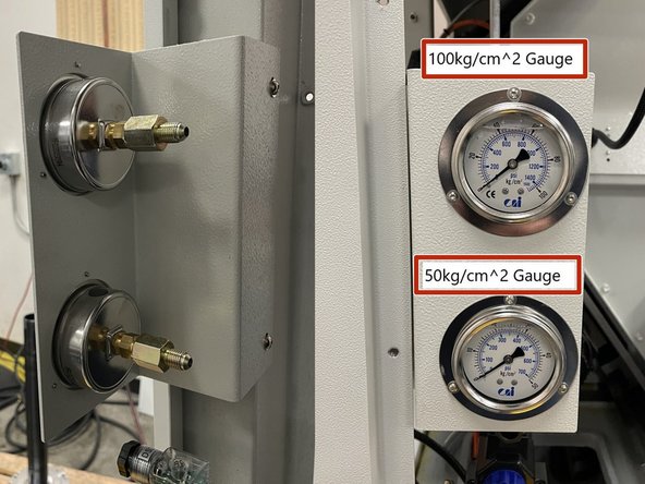
Locate the 35092-4 Gauge Bracket and both gauges. One(1) gauge is 100kg/cm^2 and the other is 50kg/cm^2. Install the gauges into the bracket with the higher pressure gauge (100kg/cm^2) in the top hole on the bracket. See Photo 1 for orientation. Install the bracket to the cabinet as shown in Photo 1.
-
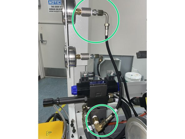
Install fittings and Oil Line P/N 35092-6 to the upper gauge and down to the right side of the manifold as shown in Photo 2. Hydraulic line orientation viewed from looking at the gauges.
-
Then install fittings and Oil line P/N 35092-8 to the lower gauge and onto the rear side of the manifold as shown in photo 3. Hydraulic line orientation viewed from looking at the gauges.
-
-
-
Now that the wiring is complete and the hydraulic lines have been connected reconnect the main power and power the machine up.
-
If a High Speed option is included in the Hydraulic Chuck Option you will need to replace the low speed high torque machine ID key and reprogram the AC Drive to use the high speed option.
-
Once the computer has booted up press the Power/ Reset button on the control panel to enable the servos. This will also start the hydraulic pump running.
-
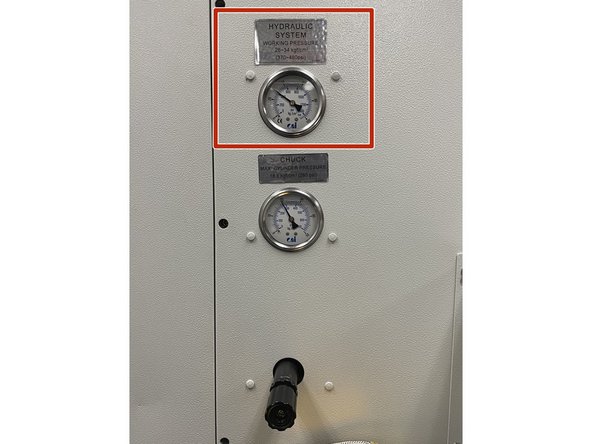
With the hydraulic pump running check the hydraulic pressure on the gauges on the left side of the machine. The High pressure should be set to between 26 and 34 kgf/cm^2. This pressure is set by the MFG and should not need to be set.
-
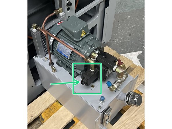
If the high pressure needs to be adjusted the adjuster is on the motor. See Photo 2
-
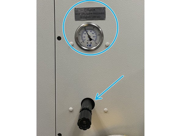
Finally the low pressure should be set to 18.5 kgf/cm^2 max. This pressure is adjusted using the adjuster that is below the low pressure gauge.
-
-
-
Clean the draw tube threads and add a light coat of anti-seize to the draw tube threads.
-
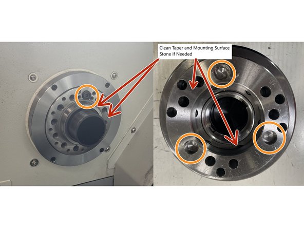
Clean the taper and mounting surface on the spindle and chuck, check for burrs or nicks, stone if needed
-
Take note the chuck has three(3) alignment holes for the drive dog. Anyone of them can be used when installing the chuck. See Photo 1
-
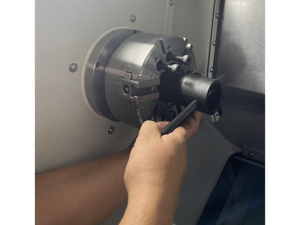
Retract the drawtube then install the chuck aligning it with the drive dog in the spindle. Using the chuck installation tool thread the chuck onto the drawtube until it stops (about 4 turns) then extend the drawtube all the way out and thread the chuck onto the drawtube until it stops again (about 5 more turns) then back it out a half a turn.
-
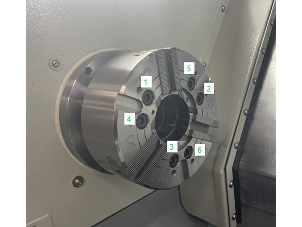
Install the six(6) M10-1.5X110 SHCS chuck mounting screws into the chuck . Following the pattern in photo 3 snug the screws for now.
-
-
-
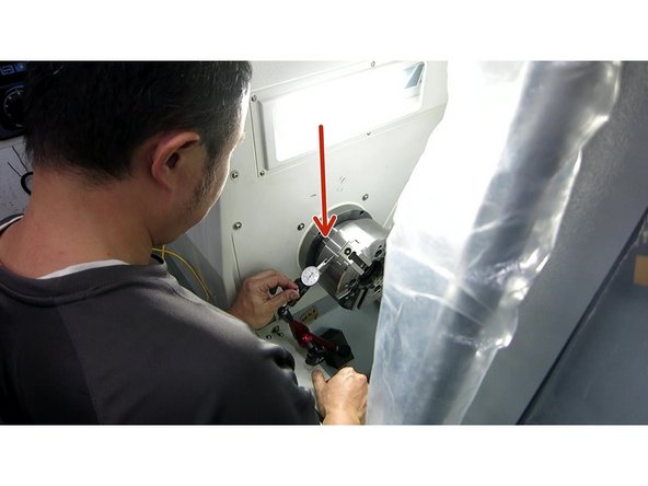
Set up a 0.0001" dial indicator on the chuck and measure the runout. The runout on the perimeter and face should be less than .0002" (5um). Tighten the six(6) mounting screws in a crossing pattern while watching the runout. Verify the runout stays in spec while tightening the screws. Torque to 58ft-lbs. See Photo 1
-
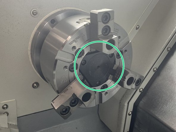
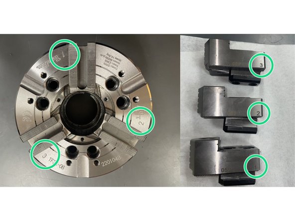
Reinstall the center cap and chuck jaws. The jaws and chuck are numbered, return the jaws to the corresponding location on the chuck. Torque the jaws to 47ft-lbs. See Photos 2 and 3
-
-
-
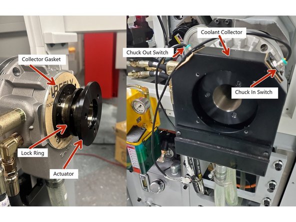
Install gasket to the hydraulic cylinder, then attach the coolant collector. Next install the lock ring to the drawbar, then install the actuator to the drawbar and tighten until it stops, then tighten the lock ring to the actuator and loosen until the 3 holes in the actuator align with the lock ring. Install the 3 screws and tighten. See Photo 1
-
Photo 1 illustrates the Coolant Collector removed to show the gasket, lock ring and actuator. Collector must be installed before the lock ring and actuator in order to install and tighten the coolant collector mounting screws.
-
Once the actuator has been installed install the Chuck In and Chuck Out sensors. Adjust them to where there is a 1mm gap between the sensor and actuator. See Photo 1
-
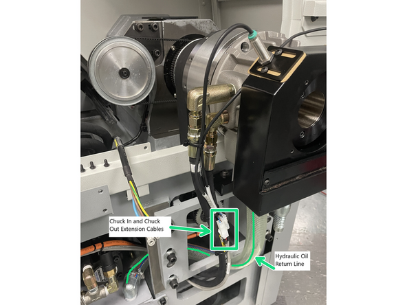
Attach oil return line to the hydraulic chuck cylinder and route as shown in Photo 2. Route Chuck In and Chuck Out extension cables to the hydraulic lines connected to the hydraulic cylinder.
-
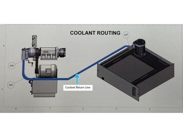
Install the coolant return line to the coolant collector and route back to the coolant tank as shown in Photo 3.
-
-
-
Once the sensor to actuator gap has been adjusted on both sensors we need to adjust the trigger point of the sensors.
-
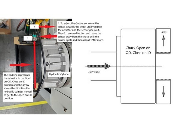
To adjust the Chuck Out sensor actuate the Hydraulic Chuck cylinder to the Chuck Open on OD, Clamp on ID position. Next 1.) move the sensor towards the chuck past the actuator until the sensor goes out then 2.) reverse direction away from the chuck until the sensor lights up, then move about 1/16" more.
-
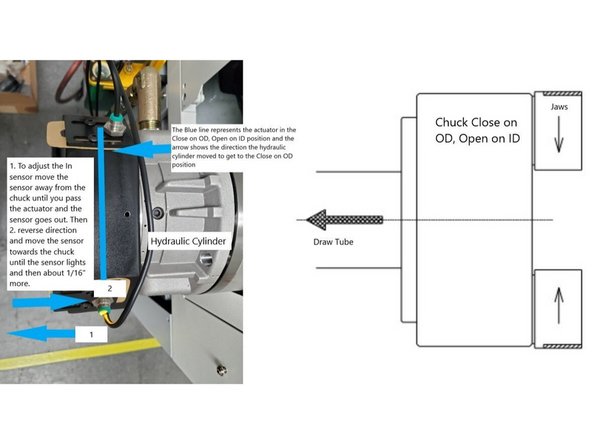
To adjust the Chuck In sensor actuate the Hydraulic Chuck cylinder to the Chuck Clamp on OD, Open on ID position. Next 1.) move the sensor away from the chuck past the actuator until the sensor goes out then 2.) reverse direction towards the chuck until the sensor lights up, then move about 1/16" more.
-
Actuate the Hydraulic Cylinder back and forth a few times to confirm the sensors are detecting the max travel of the Hydraulic Cylinder actuation. Then put a piece of material in the chuck and clamp on it and verify when the chuck is clamped on material that neither sensor is lit.
-
When the work holding device is clamping on the OD or ID of a workpiece neither sensor should be lit. The work holding device should be clamping the work piece near the center of the Hydraulic Cylinder travel.
-
-
-
Now that the chuck has been mounted to the hydraulic cylinder it should be balanced. See "30120 Chuck Balance" Dozuki procedure on how to balance the chuck. This procedure was written for the 30120 but can be applied to all lathes that require that the chuck be balanced.
-
Link to "30120Chuck Balance Dozuki Guide. https://southwesternindustries.dozuki.co...
-
Once the chuck has been balanced you can reinstall all of the covers that were removed to install the hydraulic chuck.
-
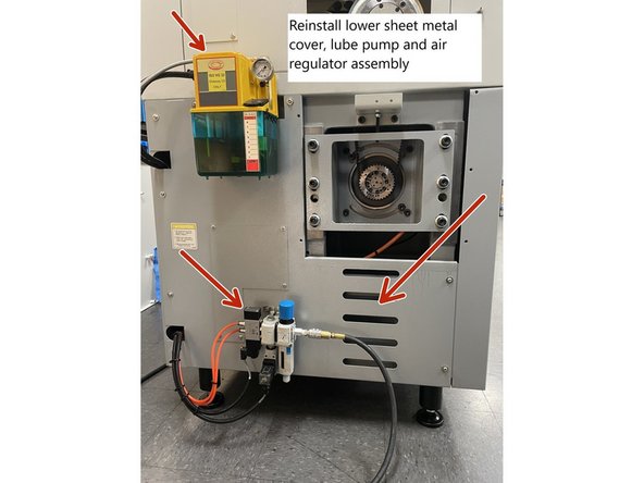
First if you remounted the lube pump remove it and reinstall the left side lower sheet metal cover. Then reinstall the lube pump and pneumatic assembly to the left side of the machine.
-
Now reinstall the upper left side sheet metal cover and the motor and belt access cover to the left side of the machine.
-
Finally install the 1 lower and 2 upper rear covers to the back of the machine. Once all of the covers have been installed wipe down the covers to remove any dirt or grease from the covers, remove and pack up all of the tools used and return machine to production.
-
Cancel: I did not complete this guide.
One other person completed this guide.


