-
-
Mount assembled air regulator to side of electrical cabinet using supplied M5 hardware (SHCS, belleville spring washer, flat washer and nut).
-
Use dimensions given to ensure clearance of knockout plate for electrical connections.
-
Remove knockout plate and replace with cable entry plate.
-
-
-
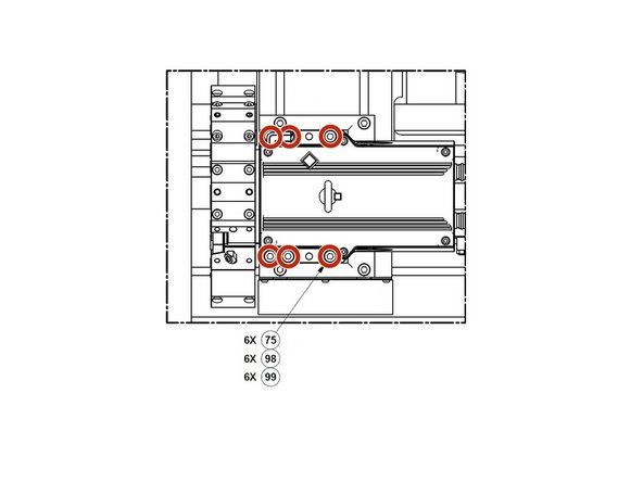
Attach turret mounting base to cross slide using the supplied M10 hardware and M10 T-slot nuts. Torque to 27ft/lbs.
-
Base must be at least 1" from edge of cross slide to avoid turret interference with sliding door.
-
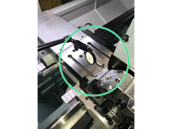
Check flatness of base to confirm it is within 0.001 T.I.R.
-
-
-
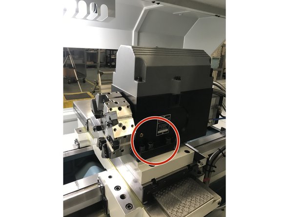
Attach turret to mounting base using the supplied M12 hardware (SHCS, split lock washers & flat washers) and lightly snug fasteners allowing ability to tram in turret. DO NOT tighten!
-
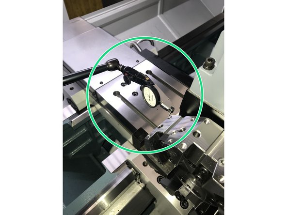
Tram in turret to 0.0005"
-
-
-
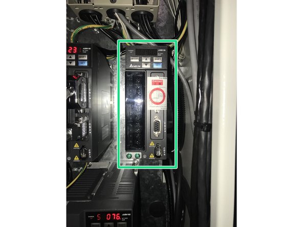
Mount Delta Drive to cabinet using supplied M4 hardware (SHCS & flat washer).
-
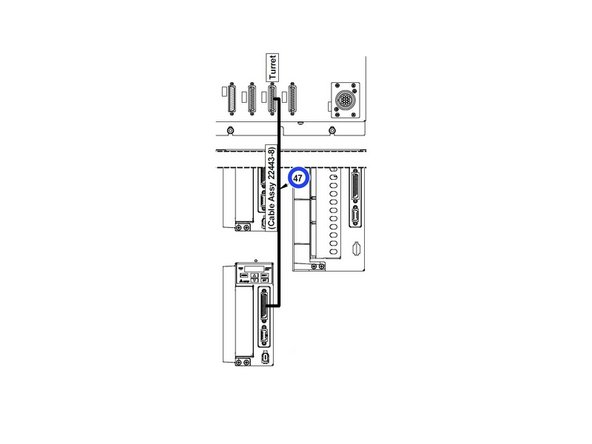
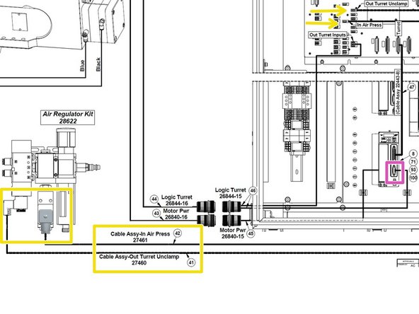
Connect logic cable from Delta Drive to Computer Module (Item 47).
-
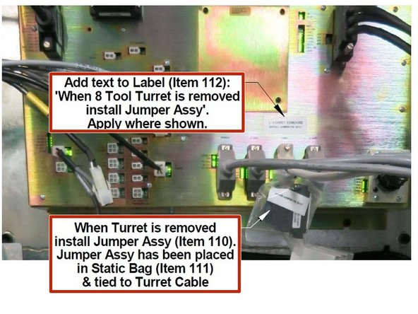
Zip tie 25 pin jumper to drive cable for turret as shown in image 3.
-
Jumper is to be used when turret is removed to prevent a fault on the Pendant.
-
-
-
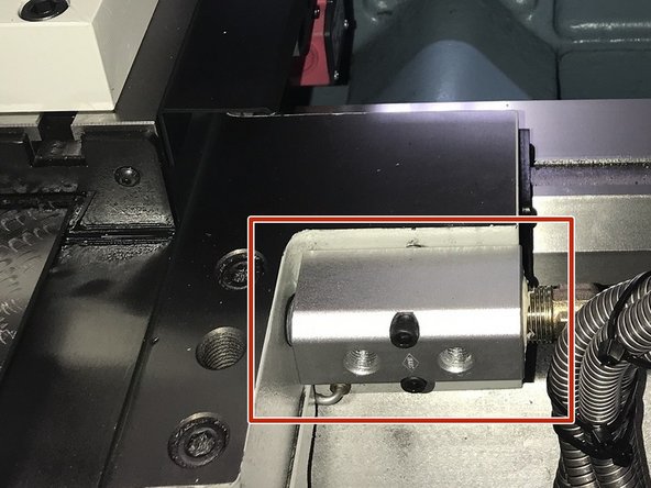
Re-locate coolant manifold to edge of carriage on 1630 and 1845.
-
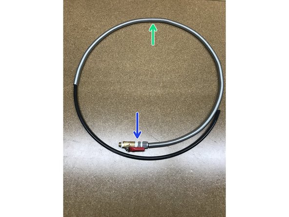
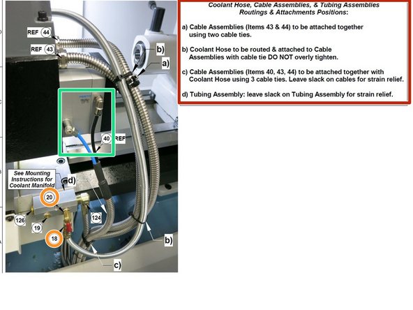
Add wire coil cover to coolant hose (turret to coolant manifold).
-
Add coolant shutoff valve to coolant hose.
-
Coolant hose may need to be trimmed slightly so it is roughly the same length as the wire coil cover.
-
-
-
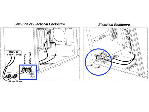
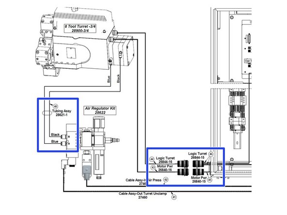
Slide internal power and encoder cables through cable entry plate into the electrical cabinet, use supplied M3 hardware to attach flange to plate.
-
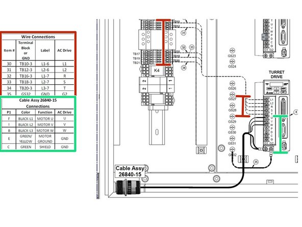
Connect internal power cable to Delta Drive as shown in wiring table.
-
Connect Motor circuit and Control circuit wires as shown in wiring table.
-
Connect Input Air Pressure cable and Output Turret Unclamp cable into respective ports on computer module.
-
Connect 9 pin logic cable into Delta Drive.
-
-
-
Attach elbow (item 20) to coolant manifold and then attach coolant hose with shutoff valve (item 18) to elbow.
-
Attach air lines to turret.
-
Route cables and hoses underneath bed toward rear of machine as per instruction in image 1.
-
Connect External Power and Logic Cables into connections on electrical cabinet. Connect air lines from turret to regulator assembly.
-
-
-
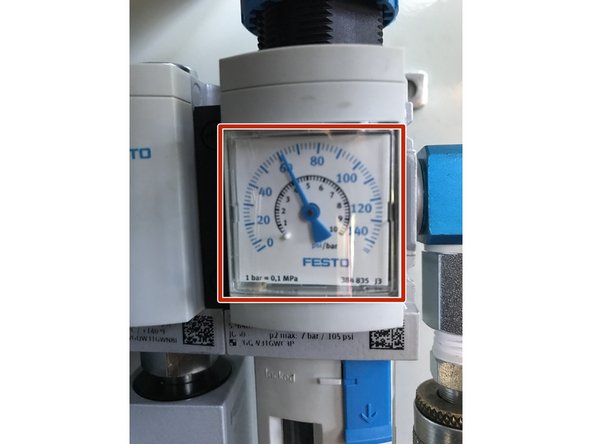
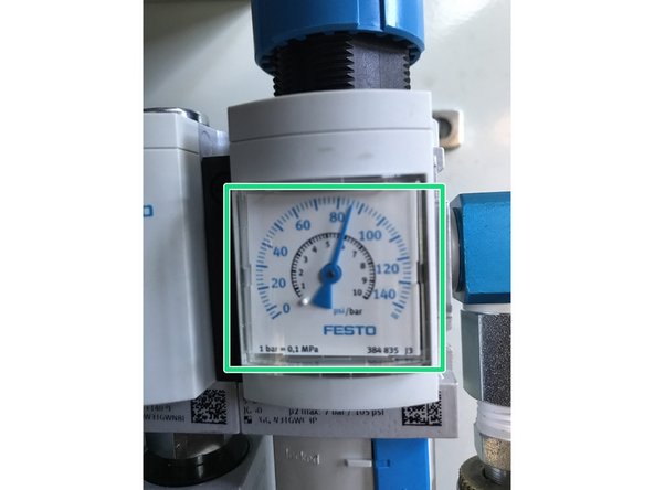
Once supply air is installed, set air pressure to 60 PSI, find the adjustment screw on bottom of pressure switch. If LED on computer module labeled "AIR-IN PRESS" is off, rotate adjustment screw until LED turns on. If LED is on, rotate adjustment screw in opposite direction until LED is off.
-
Once pressure switch is set, adjust incoming air pressure back to between 80-90 PSI.
-
-
-
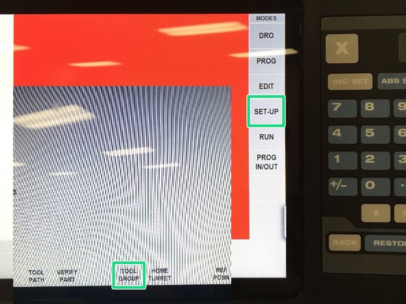
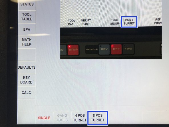
Select SETUP then TOOL GROUP.
-
Select 8 POS, then RETURN, HOME TURRET and then GO. Make sure door is closed, turret will not move if door is open.
-
Turret will begin to rotate slowly to location #1.
-
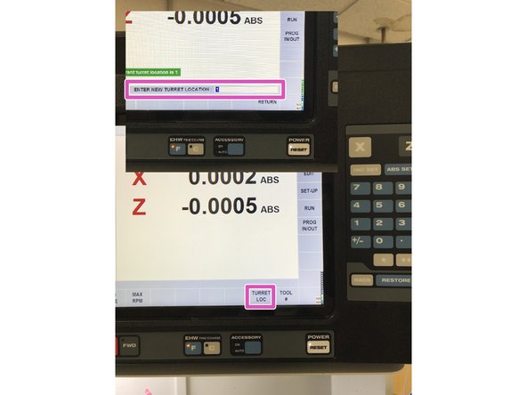
Enter desired TURRET LOC, INC SET and then GO key. Make sure door is closed, turret will not move if door is open.
-
-
-
Tram in turret to within 0.0005".
-
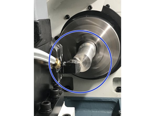
Face off a piece of cylindrical stock at least 4" long and 2" in diameter. Measure the material that is left untouched, divide by 2 and subtract no more than 0.005". Select shim stock value nearest to value without exceeding and install. Ideal final height should be between +0.002" & -0.005".
-
Re-mount and tram in turret within 0.0005" and torque fasteners down to 40ft/lbs.
-
Almost done!
Finish Line


