-
-
Separate regulator from mounting plate.
-
Use plate as a template for mounting holes of regulator. Drill 4 holes with a 0.221" diameter.
-
Top left mounting hole will be 1.25" from back of casting and 4" from underside of chip enclosure.
-
Mount air regulator assembly to side of electrical cabinet.
-
-
-
Attach tubing and armor assemblies to sheet metal, refer to document 29640-X (depends on machine).
-
Attach air lines to quick release fittings on turret, again refer to document 29640-X (depends on machine).
-
Attach sheet metal cover to turret and route armor cables downward.
-
-
-
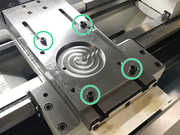
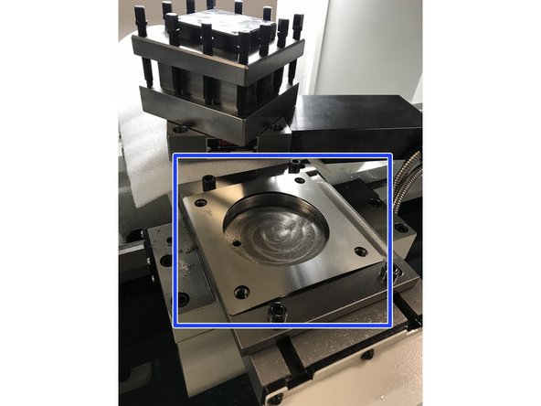
Attach turret mounting base to cross slide using the supplied M10 hardware and M10 T-slot nuts. Torque to 27ft/lbs.
-
Check flatness of base to confirm it is within 0.001 T.I.R.
-
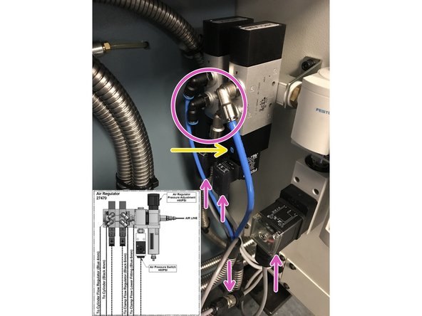
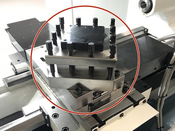
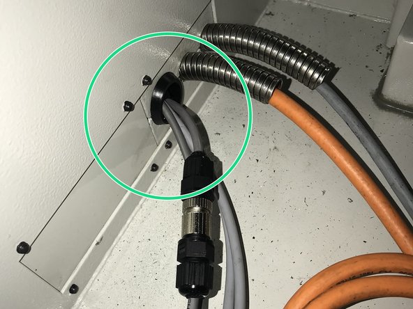
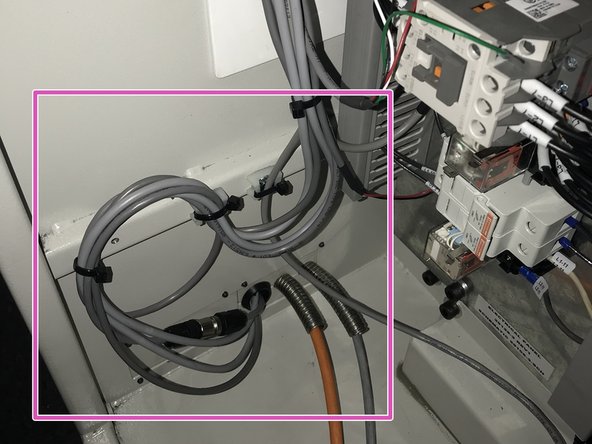
Place turret onto mounting base. Route armor cables underneath bed and exit out the rear of the chip enclosure. Attach air lines, UNCLAMP solenoid cable, INDEX solenoid cable and AIR PRESS cables to regulator assembly, refer to drawing 29640-1. Attach TURRET INPUTS extension cable to cable from turret.
-
Once air lines are attached and air supply is on, push in blue button on UNCLAMP solenoid to unclamp the turret to allow free rotation to access the 4 mounting points of the turret to mounting base.
-
Attach turret to mounting base using the supplied M12 hardware and lightly snug fasteners allowing ability to tram in turret. DO NOT tighten!
-
-
-
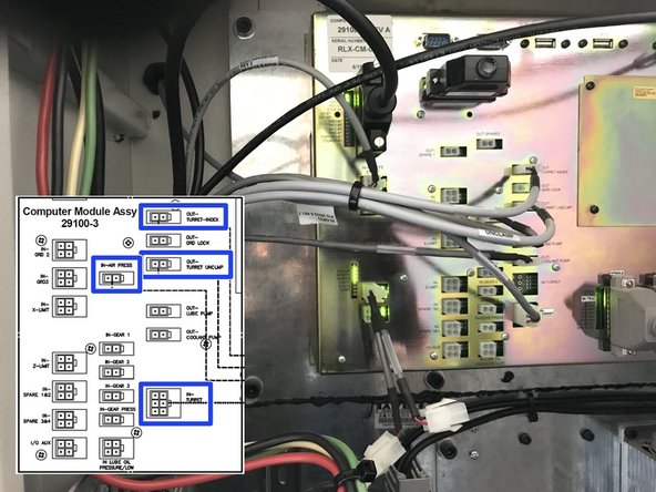
Route cables from Air Regulator Assembly into electrical cabinet as shown.
-
Connect cables from Air Regulator Assembly to Computer Module as shown.
-
Once connections are made, dress cables neatly inside electrical cabinet as shown.
-
-
-
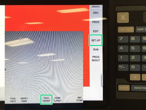
Select SETUP then TOOL GROUP.
-
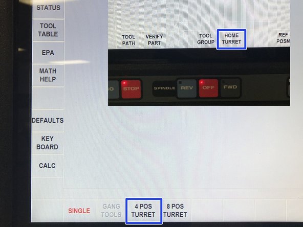
Select 4 POS, then RETURN and then HOME TURRET.
-
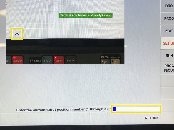
Enter current turret station location (number that is closest to the spindle) and then press OK. The turret is now ready to be operated through the Pendant.
-
-
-
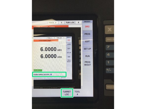
In DRO mode, select TURRET LOC, then enter desired tool station, followed by ABS SET.
-
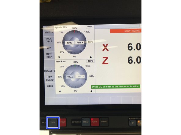
Press GO critical key on lower left corner of Pendant and turret will move to desired location.
-
-
-
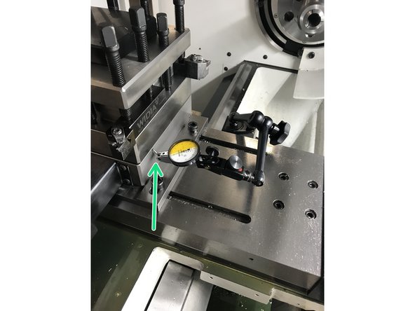
Tram in turret to within 0.001".
-
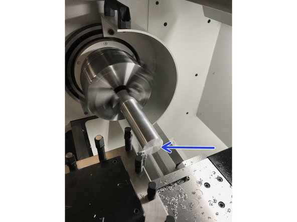
Face off a piece of cylindrical stock at least 4" long and 2" in diameter. Measure the material that is left untouched, divide by 2 and subtract no more than 0.005". Select shim stock value nearest to value without exceeding and install. Ideal final height should be between +0.002" & -0.005".
-
Re-mount and tram in turret within 0.001" and torque fasteners down to 40ft/lbs.
-
Cancel: I did not complete this guide.
One other person completed this guide.
2 Comments
We need a mounting distance for the base plate (I believe it is 1" from end of cross slide)
FST Account - Resolved on Release Reply
We need to add the pressure and air flow settings. (Monday March 25th, 2019 at 11:47 pst)
Tom
Tom Copeland - Resolved on Release Reply


