Introduction
1. Understand the different LED's on the KMX Pendant and what they are used for.
2. Understand what voltages are present in the KMX Pendant and what they are used for.
3. Walkthrough of various scenarios for aid in troubleshooting a KMX Pendant.
-
-
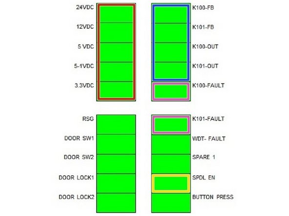
Indicator LED's 24VDC=24VDC power, 12VDC=LCD power, 5VDC=External 5VDC power, 5-1VDC=CPU power, 3.3VDC=Apps board logic power,
-
If one or more LED’s above are not on, there is a power problem on the pendant and the pendant/computer module will most likely need to be replaced. Check power connector and reboot to see if this solves the problem.
-
Indicator LED's cont. RSG=RSG indicator (ON=button pressed), DOOR SW1=Door guard switch 1 indicator (ON=switch closed, switches are wired normally closed), DOOR SW2=Door guard switch 2 indicator (ON=switch closed, not used on USA mach.). DOOR LOCK1=Door lock 1 state indicator (ON=lock engaged). Not used on USA machines.
-
Indicator LED's cont. DOOR LOCK2=Door lock state indicator (ON=lock engaged). Not used on USA machines.
-
The 4 LED’s below should be on when the e stop is not pressed and you are in DRO mode. If one or more of these LED’s are off in this condition, then there is an internal problem with the pendant/computer module and the pendant will most likely need to be replaced.
-
Indicator LED's cont. K100-FB=K100 relay feedback indicator (ON when K100 contacts are closed), K101-FB=K101 relay feedback indicator (ON when K100 & K101 contacts are closed).
-
Indicator LED's cont. K100-OUT=K100 relay command indicator (ON when system is commanding K100 contacts to close). • Unexpected power (K100-FB) when relay should be OFF (Welded contacts) • Unexpected loss of power (K100-FB) when relay should be ON (ESTOP pressed, relay not working)
-
Indicator LED's cont. K101-OUT=K101 relay command indicator (ON when system is commanding K101 contacts to close). • Unexpected power (K101-FB) when relay should be OFF (Welded contacts) • Unexpected loss of power (K101-FB) when relay should be ON (ESTOP pressed, relay not working, K100 relay opened contacts unexpectedly)
-
-
-
The K100 and K101 fault LED’s below will be on when relays K100 or K101 are in an unexpected condition. Only two possible causes for a fault: 1) E-stop circuit interrupted (Examples: Estop button pressed, Euro Estop bypass connector loose or missing). Fix the interruption and condition can be cleared.
-
2) Welded relay contacts. Will continuously fault after attempting to clear condition. Would a USA customer get into this condition if there machine is behaving correct? No. If there is a fault the machine will have no 110VAC power to motors, coolant, and spindle enable.
-
Indicator LED's cont. K100-FAULT=K100 relay fault indicator (ON = Fault Detected). K101 FAULT=K101 relay fault indicator (ON = Fault Detected).
-
Indicator LED's cont. WDT-FAULT=Watchdog fault indicator (Slow blink 1 sec on/1 sec off = Normal operation), (Fast blink 5 time/sec = Watchdog fault occurred). If this occurs, reboot to see if the problem is solved. If not, the pendant/computer module will most likely need to be replaced.
-
Indicator LED's cont. SPARE 1=Unused, SPDL EN=Spindle enable indicator (ON = Spindle Enabled). Should be on when in DRO or RUN modes, which allows you to turn on the spindle. BUTTON PRESS=ON when any overlay button is pressed. This verifies all overlay keys are recognized. Service code 81 can also be used.
-
-
-
Make sure 110 volt power is getting to pendant. If no LED lights are on at rear of pendant, check main fuse on pendant power switch. Check 24VDC LED, should be ON. If not possible causes are: • Bad 24VDC power supply.
-
Check 12VDC LED, should be ON. If not possible causes are: • Bad 12VDC power supply. Check 5-1VDC LED, should be ON. If not possible causes are: • Bad 5-1VDC power supply.
-
Solutions 1. If fuse is blown in main power switch, replace fuse. 2. If fuse is not blown, replace the computer module.
-
-
-
Check Button Press LED while pressing any overlay key, LED should light while button held down. If not possible causes are: • FPGA not programmed. • FGPA not running for some reaso
-
Check WDT-FAULT LED, should be blinking slowly. If not, possible causes are: • Master software crashed or is not running. Check 5-1VDC LED, should be ON. If not possible causes are: Bad 5-1VDC power supply.
-
Check 12VDC LED on pendant to see if power is getting to the LCD. If it is not, replace computer module.
-
Solutions 1. Reboot pendant and see if problem goes away. 2. When rebooting pendant, please note if bios screen is present while booting. If it is, then the LCD should be good, replace computer module as required if the screen comes up blank.
-
Solutions cont. 3. FST’s can check connections inside of pendant before replacing parts. 4. If screen is black (no backlight) and you do not see bios either, then replace pendant. We can't tell if it is the LCD on pendant enclosure or the computer module. Note – if you orientate the 12 pin LVDS cable wrong, then you can get a black screen.
-
-
-
Check RSG LED, should light when RSG button is pressed. If not, possible causes are: • Bad RSG switch. • Bad RSG circuit.
-
Solution If you suspect the RSG switch, plug it into the CBB (if you have one) where the single input limit switches are found. Then turn on single input limit switches and you should see a change of state on the screen in DRO when the switch is pressed. If you do, the switch is good and the computer module should be replaced.
-
-
-
Check Button Press LED while pressing any overlay key, LED should light while button held down. If not possible causes are: • FPGA not programmed. • FGPA not running for some reason. • Overlay connector has come loose.
-
Check WDT-FAULT LED, should be blinking slowly. If not, possible causes are: • Master software crashed/not running. The beeper is run by the master software. If master is running the beeper should work. If WDT-FAULT LED is blinking fast, then the master and operating system has lost communication.
-
Solutions 1. Reboot system and see if problem still exists. 2. If Button Press LED does register with any button presses, check overlay connection point if you can. Otherwise the computer module most likely needs to be replaced.
-
Solutions 3. If some overlay keys register but not all, then replace the pendant enclosure as the overlay may have a problem. You can use service code 81 as well to check overlay.
-
-
-
Check Door SW1 LED for USA machines when you open and close the door. Door SW2 LED is not being used. They should change state when door is open/closed. If not, possible causes: • Improperly installed switch. • Cable not properly connected • Bad switch • Bad cable
-
Solutions If the switch and cable check out OK, then replace computer module.
-
-
-
(If only 1 motor has a problem then swap cables to determine if it is the motor or computer module.) Assumes pendant is powered up so main fuse is good. Check all power LEDs (24VDC, thru 3.3VDC), they should be ON. If not possible cause is the respective power supply is bad.
-
Check WDT-FAULT LED, should be blinking slowly. If not, possible causes are: Master software crashed or is not running. Check K100-OUT and K101-OUT LEDs, they should be ON. If not, the system is not turning relays on as expected.
-
Check K100-FB and K101-FB LEDs, they should be ON. If not, possible cause bad respective relay. Check K100-FAULT and K101-FAULT LEDs,, they should be OFF. If not possible causes could be: • ESTOP pressed • Respective relay not working.
-
Solution Replace Computer Module
-
-
-
Check SPDL EN LED, it should be ON. If not the system is not enabling the spindle as expected. When going in and out of DRO mode should make a relay click pendant. If it does not click, then then the relay is most likely bad.
-
Check all power LEDs(24VDC, thru 3.3VDC), they should be ON. If not, possible cause is the respective power supply is bad. Check WDT-FAULT LED, should be blinking slowly. If not, possible causes are: Master software crashed or is not running.
-
Check K100-OUT and K101-OUT LEDs, they should be ON. If not, the system is not turning relays on as expected. Check K100-FB and K101-FB LEDs, they should be ON. If not, possible cause bad respective relay.
-
Check K100-FAULT and K101-FAULT LEDs,, they should be OFF. If not possible causes could be: • ESTOP pressed • Respective relay not working.
-
Solutions 1. If spindle enable is not working or K100-OUT and K101-OUT LED’s are off or other LED’s mentioned above are not working, replace computer module.
-
Solutions cont. 2. If item 1 is performing like it should, then the problem may lie in the electrical box (relay module) DPM upgrades or in the 20676 electrical box.
-
Solutions cont. On the DPM, the E stop OUT LED #7 should be on when the spindle is enabled. If it is and the spindle still does not come on, then the relay module does not have power, the fuses may be blown or the overload may be tripped. Troubleshoot accordingly.
-
-
-
Please also see "System does not respond to button presses" above For lock up symptoms, it is important to gather enough information to understand what the customer is referring to. We normally need to identify if our hardware or software is locked up or if the operating system is locked up.
-
Check This Plug in a USB keyboard and confirm if the mouse or keyboard is recognized. If it is, the operating system is still functioning. At this point, you can verify if the operating system and master software have lost communication by the status of the Watchdog LED light.
-
Check This cont. If the operating system is still functioning, then the problem lies with our software or our hardware.
-
-
-
Make sure the KMX bypass jumper is plugged into the port labeled Euro E stop. If it is not plugged in, then you will get a constant stop message once we implement this feature in software. See drawing 29819 (Steps 10 & 11 in KMX Upgrade Inst.) for where this adaptor plugs into.
-
-
-
Early on in the KMX development, we found that intermittently USB devices were not always recognized when they were plugged in. At times we had to switch ports or unplug and replug for it to be recognized.
-
Several KMX Pendants were observed to have intermittent issues with recognizing USB drives. Removing the drive and reinserting it, or inserting it into the other USB port seemed to solve the problem. It was difficult to reproduce the failures and would seem to work for some time before a failure would occur again.
-
Issue was also observed at some beta sites where cheap USB drives were used and consistent failures were observed.
-
The root cause of the problem was an inductor on the mother board that was supposed to be removed from production boards but was forgotten. Removal of the inductor (L29) fixed the problem.
-
The solution will be found on REV D pendants. If a customer complains about this problem, then replace the KMX computer module, part number 29850-1.
-
-
-
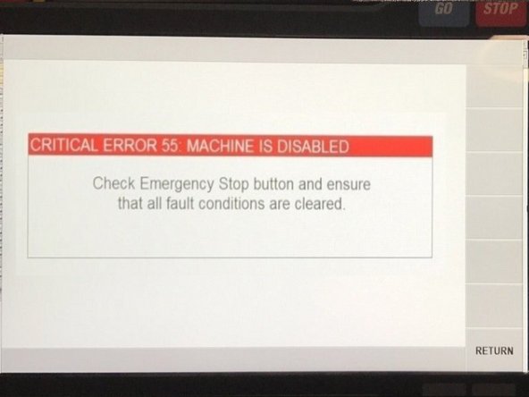
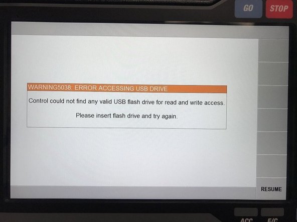
The symptom explained in step 12 can lead to a failure during the software download process. When this failure happens, the following message will be seen on the screen.
-
Attempting to reboot the pendant would result with the same error appearing, and the KMX software would no longer launch again. This failure is more likely to happen on REV C pendants are older due to a USB problem on the motherboard.
-
When this failure happens, it can be corrected without changing the pendant or computer module. The user will need a keyboard. See instructions in Step 14.
-
-
-
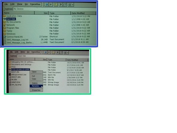
The state of this pendant can easily be fixed by replacing the contents of the PTCE-20180115-1005 folder into the PTCE folder, and then rebooting the computer. User will need a mouse / keyboard to navigate Windows CE 6.0. For the original scenario above, the steps would be as follows:
-
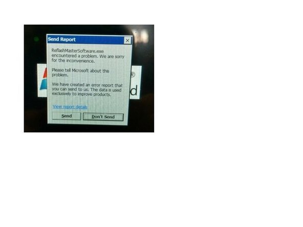
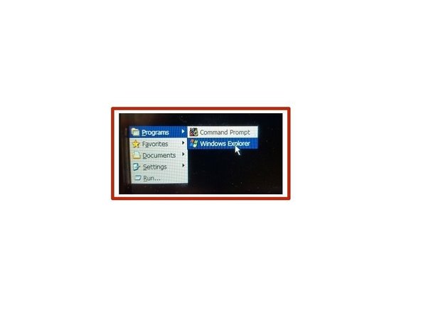
1) Plug in mouse and keyboard. The USB flash drive is no longer needed at this point. 2) Click on the SEND button to get rid of the error message. 3) Press CTRL + ESC to bring up the STAR T menu in Windows 4) Navigate to Programs and then click on Windows Explorer.
-
5) Double click on the HARD DISK
-
6) For this scenario, right-click on the PTCE folder and choose DELETE. It is incomplete, and possibly corrupted anyways.
-
8) Cycle power to the KMX pendant, and it should boot up normally again.
-
-
-
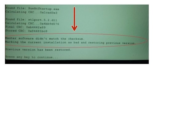
However, keep in mind that the symptom may vary due to the nature of the underlying problem. It’s possible that the software update could finish copying over the software, but then fail the CRC check. It would look something like Image 1.
-
At this point, a user can simply cycle power to his pendant (or press any key on a keyboard, as displayed) and the system should revert back to the original software version. It will also create a PTCE-BAD folder, in case we wanted to examine it.
-
Another possible symptom is that after a user plugs a USB flash drive into the KMX pendant, the flash drive will remain unseen for several seconds, or remain unseen altogether.
-
For both of these cases above, it is recommended to try the other USB port, or try another flash drive altogether.
-


