-
-
ESTOP machine and unplug 220V.
-
Set machine in high gear to highest RPM.
-
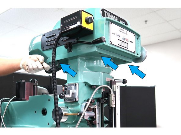
Remove plate below the motor by removing 3 M6 SHCS.
-
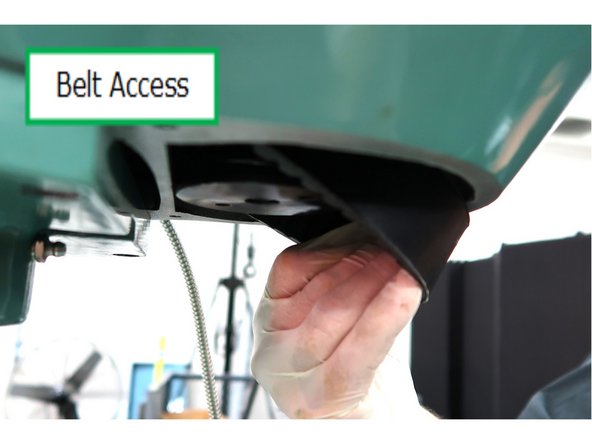
With the cover removed, you have access to the spindle belt.
-
-
-
Disconnect wires at spindle motor electric box. Leave wrapped cable attached to electric box in rear.
-
Remove 4 M10 SHCS from head. Screws will be reused with larger washers.
-
-
-
Head motor is heavy, proper hoist procedure should be used to lower head from machine. Refer to videos later in this guide about the installation and removal of spindles.
-
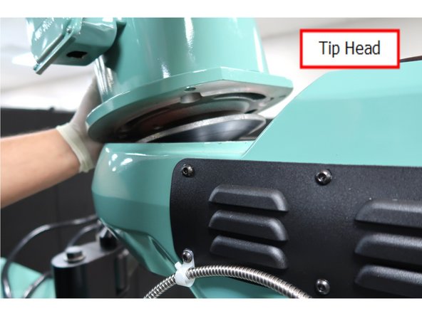
Carefully tip motor back .....
-
...which allows the spindle belt to fall off the pulley and be accessed from below.
-
Verify belt separated from pulley. Set motor back down on machine. Use proper hoist to remove motor from machine. See Steps 16,17 and 19 for information to connect a hoist to the spindle motor and to use it.
-
-
-
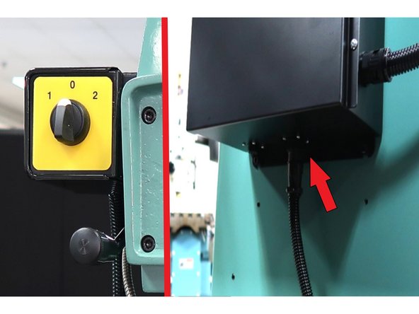
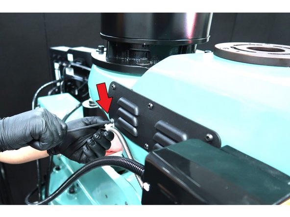
Remove spindle switch by disconnecting this cable at the bottom of the electrical box and any tie wraps or connections along the cable.
-
Remove glass scale cable for now.
-
-
-
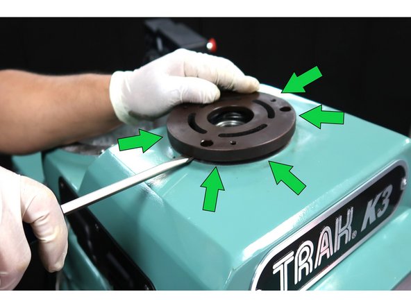
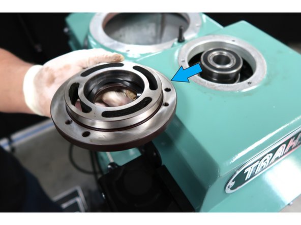
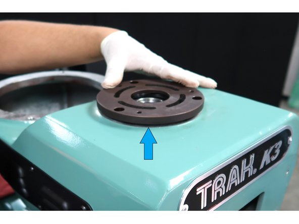
Loosen and remove 3 SHCS from the bearing plate.
-
Carefully pry around the plate to lift it off the machine.
-
Remove the plate from the machine.
-
-
-
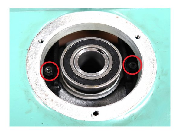
Locate the 2 SHCS below the bearing plate.
-
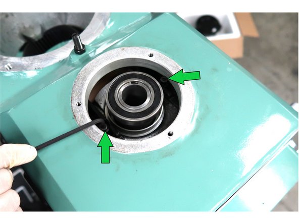
Loosen and remove the 2 SHCS.
-
Remove 6 M8 SHCS, from the upper head cover three of which are shown.
-
-
-
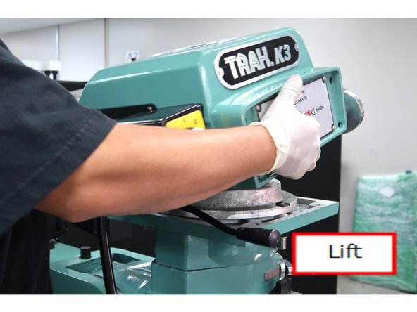
Lift upper head cover from machine.
-
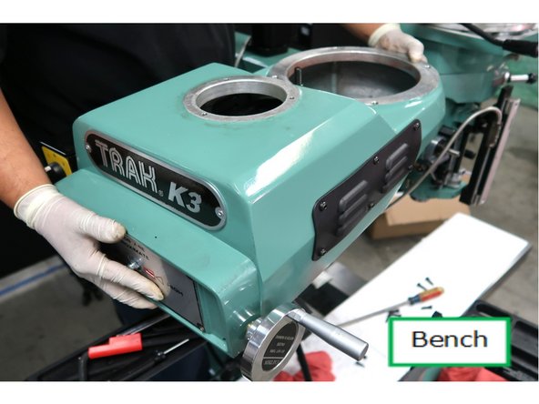
Set it on a workbench for further disassembly.
-
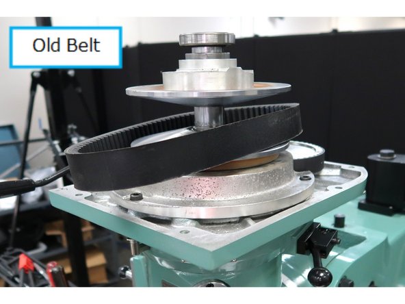
You are left with this from under the upper head cover. Remove the belt.
-
-
-
Push the upper half of the pulley down for access. To prevent damage to the parts, 1 - use a bearing puller to remove the bearing. 2 - Remove the snap ring, 3 - by using snap ring pliers.
-
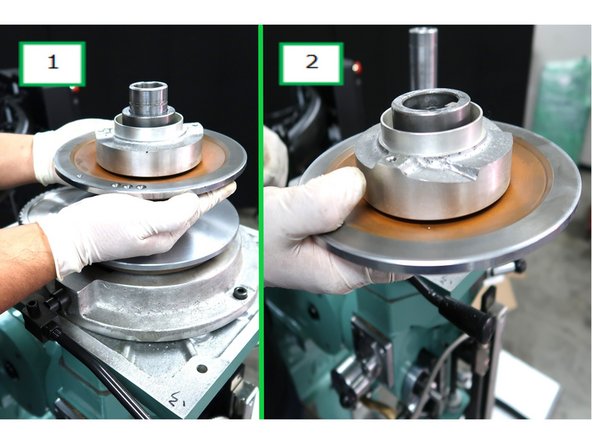
1 - Slide off the upper half of the vari-disc. 2 - Remove from machine.
-
-
-
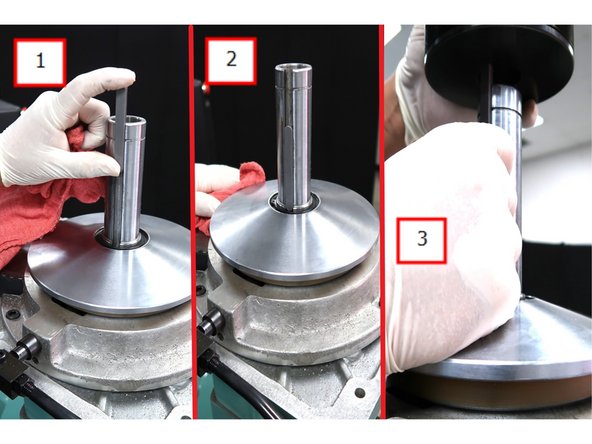
1 - Slide key P/N 24169-1 into keyway. 2 - Set key into position. 3 - Hold key as you press the new pulley P/N 23632 into position all the way down touching the vari-disk.
-
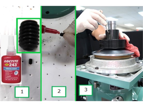
New pulley in position. 1 - Use primer less Loctite 243 on the setscrew. 2 - Apply to threads. 3 - Tighten the setscrew against the key.
-
Using Loctite with typical light oil coated fasteners will work. Blue stripe on bottle means the Loctite is removable.
-
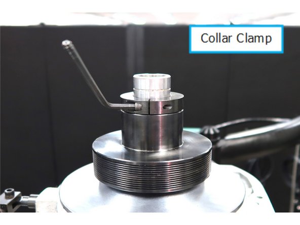
Install the collar clamp P/N 24172-1 with the slit at 180° away from the shaft keyway. Push down against the pulley and tighten. Replace the snap ring.
-
-
-
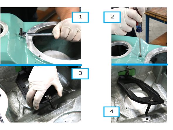
1 - Loosen and remove nut. 2 - Tighten stud into upper head. 3 - Remove stud from threads. 4 - Hold while flipping to access the top of upper head.
-
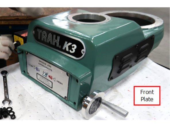
Remove front plate and retain the screws.
-
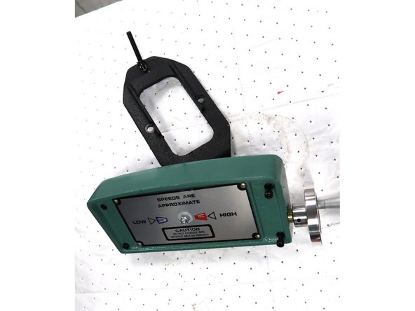
Remove old assembly.
-
-
-
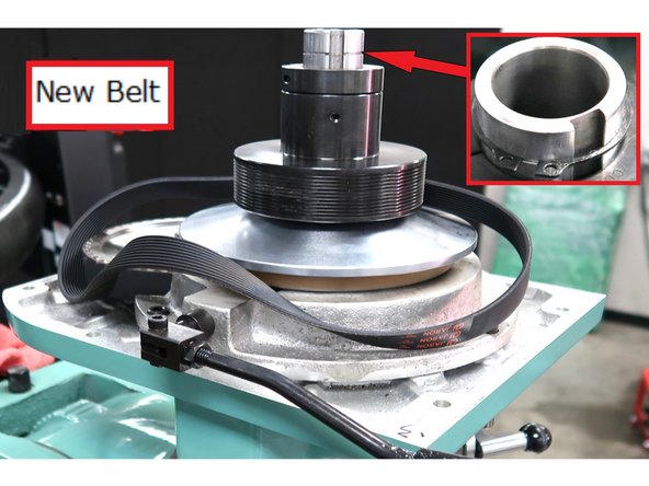
Add new spindle belt P/N 23597 . Replace the snap ring as shown by inset photo.
-
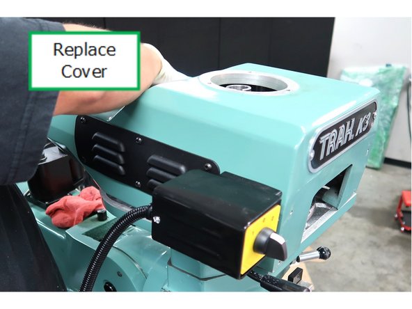
Replace the upper head cover. Replace the 6 M8 SHCS in the head cover just loose for now.
-
Press the bearing back into the bearing cap and then press it back on the machine.
-
-
-
Remove the nut on the front.
-
Remove the speed chain with a small mallet from the front.
-
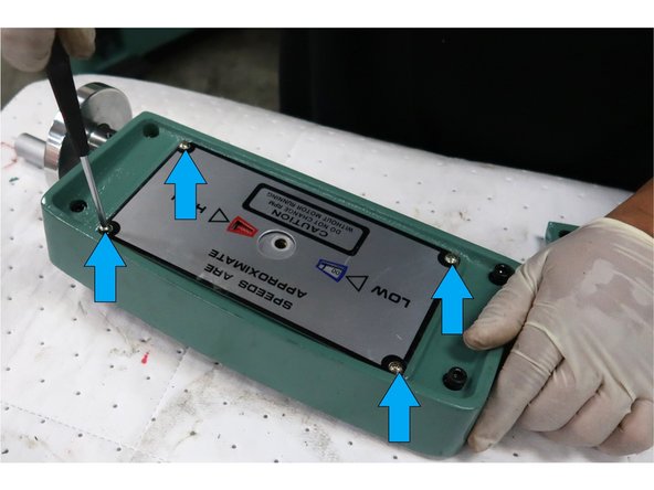
Remove the four Philips head screws to remove the front plate and speed dial.
-
-
-
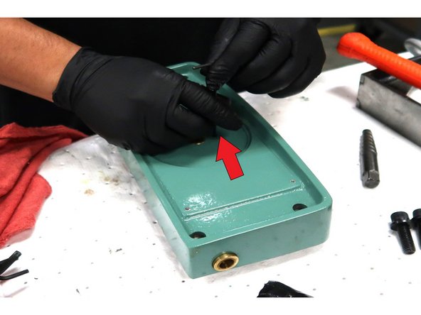
Behind the plates, there are two set screws in the same hole. Remove both of them.
-
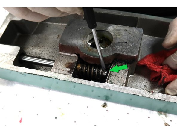
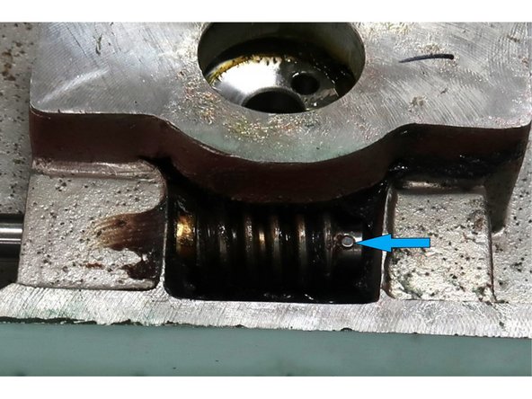
Remove excessive grease around the gear and look for pin through the shaft.
-
Close up of pin without grease.
-
-
-
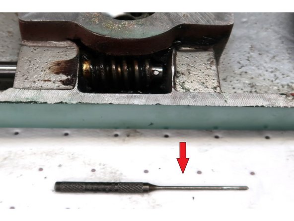
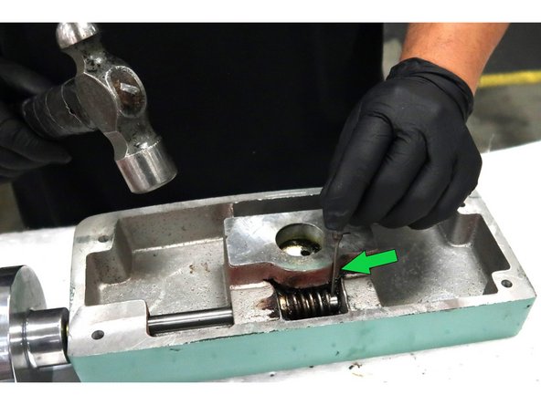
Use a 3/32 punch to remove 3/15 roll pin in speed change gear.
-
Align punch
-
1 - Spin the handwheel to see exposed pin. 2- Remove roll pin which will allow you to remove speed change handwheel with the shaft and then remove the small floating gear. Wipe excess grease from gear.
-
-
-
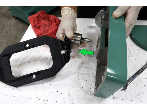
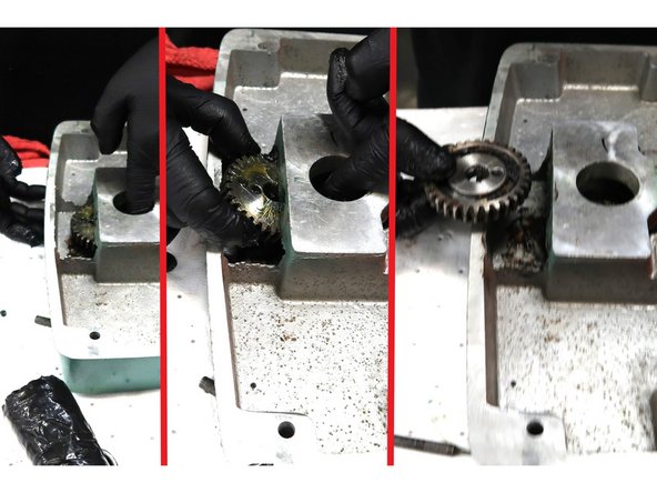
Use finger to slide speed change gear towards the edge of the plate and use other hand to remove gear. Clean excess grease.
-
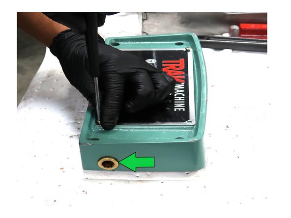
Install the new front nameplate P/N 23965-1 using the old screws. Punch out original plug from the rear and replace with plug P/N 24164.
-
-
-
This is a very heavy motor use proper lifting equipment to install motor on machine. See video provided.
-
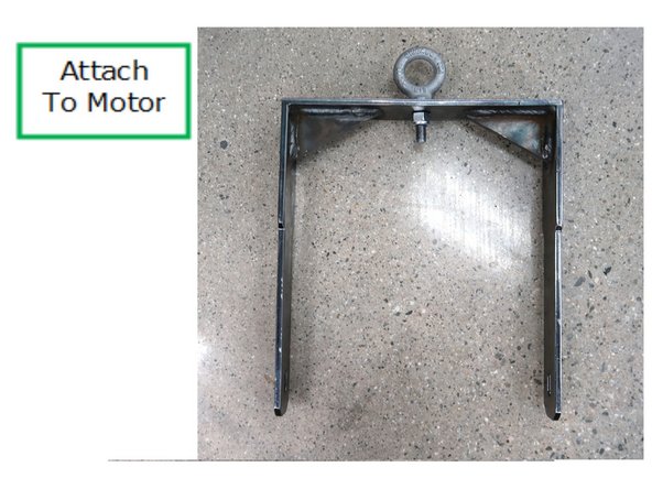
Use this provided bracket with a shop crane to lift motor in position.
-
Attach bracket to P/N 24162-1 motor using two M8-1.25x25 20B SHCS to secure the bracket to the motor.
-
-
-
This is a very heavy motor use proper lifting equipment as shown here.
-
Lift and position new spindle motor on top of the machine.
-
-
-
This is a heavy spindle. Use proper equipment to install. See video on the next step placing the spindle on the machine.
-
Electrical connections for the motor go on the left side of the machine. Remove the two M8 SHCS holding the bracket to the motor. Attach the spindle belt through the access hole below the motor, slide motor as needed. Slide the motor in position to align with the support holes.
-
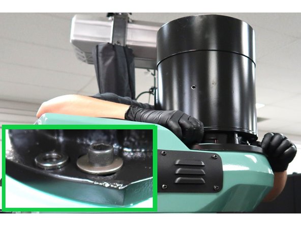
Reuse the same SHCS removed from the old motor except use supplied larger washers. Inset photo shows the original washers with the larger replacements in use.
-
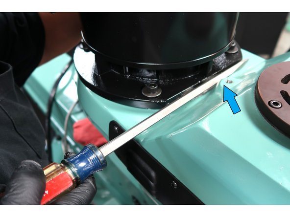
Slide the motor toward the rear of the machine to make the belt tight and tighten the four bolts securely. Use pry bar as needed to make the belt tight.
-
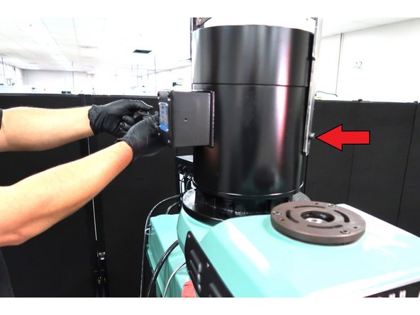
Verify the spindle belt is tensioned properly by accessing the belt through the black side panel. Verify spindle belt tension is 7 lbs. with 0.15” deflection, adjust belt if necessary. Use belt tension meter (Example: Bando Tension Master Model VA-010) to measure tension.
-
-
-
Video shows our operator installing the new spindle motor into the upper head cover of the machine.
-
-
-
Reattach glass scales cable support.
-
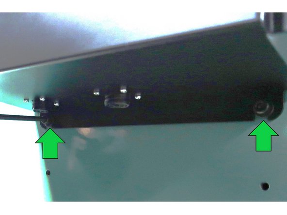
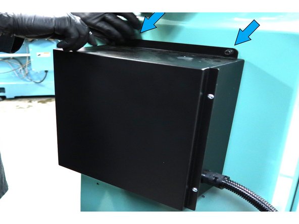
Disconnect any cables on the left side of electric box. Loosen the two screws on the bottom of the box.
-
Remove the two top screws and remove the existing electric box with the old motor cable.
-
-
-
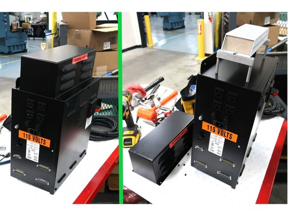
The new box is taller than the old box. The new holes are pre drilled, so move the bottom screws down.
-
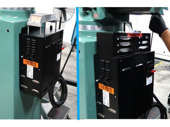
Make sure the bottom screws for the electric box have two washers each. The box will slide in between the two washers and rest there while you attach the top screws.
-
New P/N 24060-4 electric box needs to have the top cover removed to attach the top holes of the electric on to the back of the machine.
-
Attach the electric box, insert and tighten the top screws and replace top cover. Tighten lower screws.
-
-
-
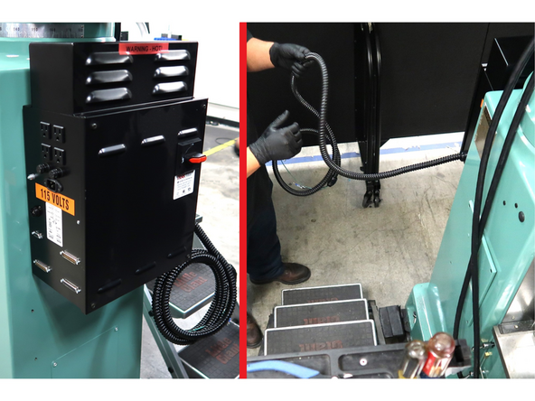
New electric box comes with spindle motor cable attached. Unwind it and route it properly.
-
Open junction box.
-
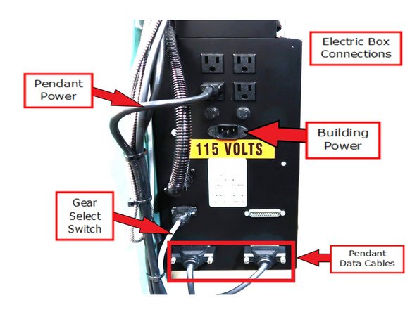
Pull wires through the bottom opening and attach connector. Three main wires to attach plus ground.
-
Inset photos show a sample of wire labels and the jumper locations for low voltage use.
-
-
-
Two red and two black wires. Next attach a red wire with a black wire and create two pairs.
-
Cut off exposed wire with the red sheathing. Use wire strippers to strip equal lengths of sheathing from all of the wires. Wrap them together as red and black pairs secured with wire nuts.
-
1 - Wrap each pair with electrical tape. Wrap both pairs together with tape. 2 - Neatly pack electric box. 3 - Close and secure box.
-
-
-
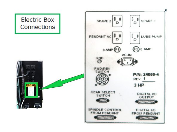
Connect spindle forward reverse switch cable. FYI: There is a decal with cable locations to the right of this connector.
-
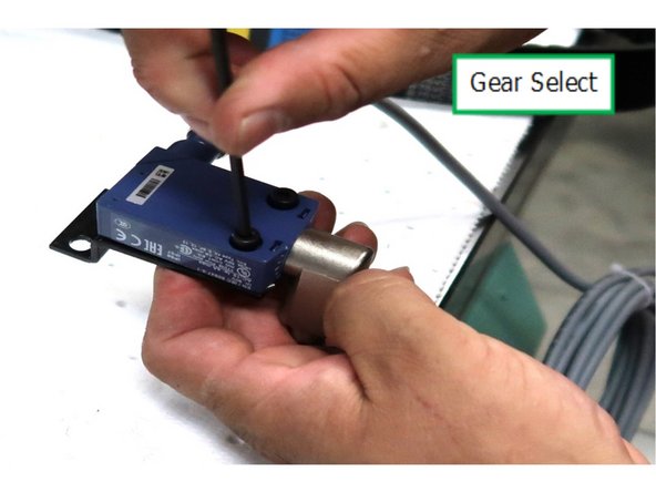
Assemble the bracket P/N 23969-1 on the limit hi/lo gear select switch P/N 23968.
-
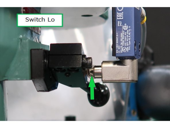
You want the wheel to hit the speed lever when the spindle is in low gear to activate the switch.
-
-
-
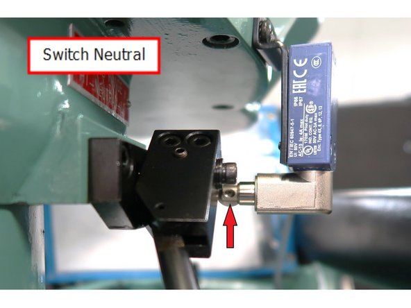
Switch must be carefully aligned before drilling holes in casting. The switch is in neutral position and note position of switch plunger.
-
With the handle moved to the neutral position, note the slight throw of the plunger. There is only a couple millimeters difference in the position of the switch. The switch needs to be located properly to work.
-
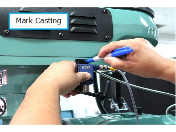
Check location twice and mark the two casting locations to drill. Use 10/32 bit to drill the hole and hand tap the 10/32 hole . Attach bracket to casting using two M4-0.7x16 25B SHCS.
-
-
-
WARNING: Incorrect connection will cause damage to spindle electronics and may damage the pendant. Connect external devices according to diagram P/N 29096 posted here.
-
Make connections as shown.
-
Reference decal or text on components for wire locations.
-
Make sure you have right pendant for Spindle Control P/N 29006-6. Use different pendant connections based upon either breakout box or spindle control usage. You may print out this drawing P/N 29096 available at the end of this guide.
-
-
-
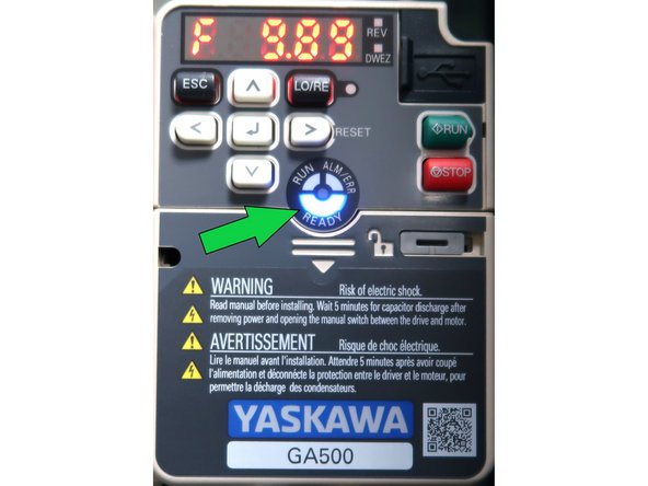
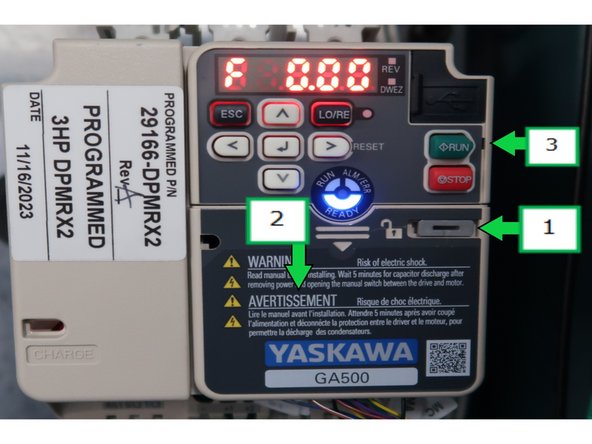
The AC Drive should be programmed when you receive it for installation. You can verify if it has drive parameters downloaded upon boot up of the machine by looking at the drive face. It will either show an error code and an error light, the ready light or the flashing run light. Notify manager if AC drive not programmed.
-
You could also try to operate the spindle. If it does not move, there are likely no drive parameters loaded.
-
ERR/Alarm - Error code displayed. Light on solid shows either a drive fault or the E-STOP has been activated. Clear E-STOP should clear error and change to either Run or Ready. If not, likely a drive fault.
-
Ready light displayed. Means ready for operation no faults.
-
Run light displayed. Means ready for operation and waiting for an operational command.
-
If the drive operates, but has problems, you could download the latest AC Drive software from SharePoint using Steps 28 - 30.
-
For further information download GA500 AC Drive technical manual from www.yaskawa.com
-
-
-
For a field install, we suggest you download the needed drive program file where you have SharePoint access before traveling to the installation site.
-
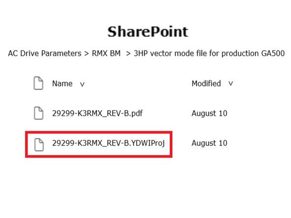
Access SharePoint > Operations > Manufacturing > Machine Assembly > AC Drive Parameters > RMX BM which gives you the directory shown. Download the highlighted file.
-
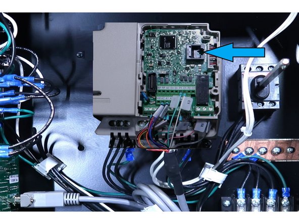
Power up the machine and open the electric cabinet door. In order to access the download port, 1 - Slide lock to the left with a small screw driver. 2 - Push down in the center of the lower cover and pull away from the drive. 3 - Push upper cover slightly to the left and remove it from the drive .
-
Connect the download cable to the port as indicated.
-
-
-
Run Drive Wizard Industrial from your laptop. Press Open from the top menu.
-
Select the file to down load 29299-K3RMX_REV-B from your computer. Press Open from the lower right corner of the screen.
-
Project screen will display and press Ok.
-
-
-
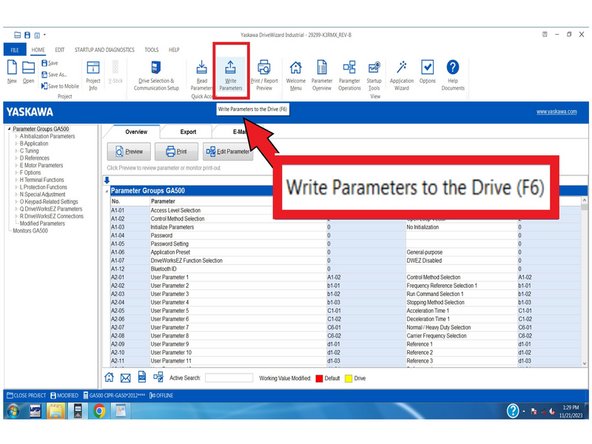
Press Write Parameters from the top menu.
-
When the program completes the down load. Remove cable and reboot the machine.
-
-
-
Gradually speed up the spindle to 5,000 RPM. The initial install will likely have some unwanted noise.
-
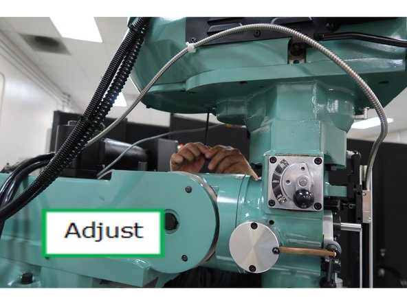
To adjust, loosen the bearing cap. Move the upper cover around slightly until the sound of the spindle sounds normal and tighten down the 6 SHCS using a cross pattern . When done with the alignment, make sure the top cover and bearing cap screws are securely tightened.
-
See the next step for a video showing the alignment in action.
-
-
-
Video gives you an idea of how to adjust the bearing cap, loosening and tightening of the screws to align the upper cover.
-
Almost done!
Finish Line


