Introduction
This guide is designed for TRAK FSTs to be able to easily install work lamps on any lathe. The first four steps explain the installation procedures. The remaining steps provide the specific details and measurements for our 1440, 1630, 1630HS, 1845, 2470 lathes.
-
-
These are instructions to install lamps on TRAK Lathes. Specific drawings and dimensions will be shown on the pages for each lathe later in the guide. PDF files for the lathes are included at the end of this guide.
-
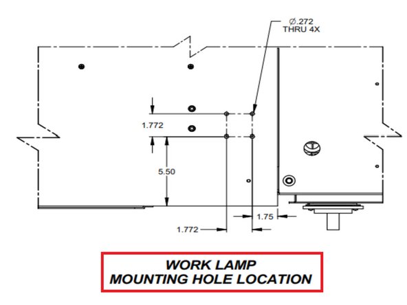
Refer to the drawing for measurement locations for the outside lamp. Photo shows plate included with kit used below the lamp for strength. Screws will be installed from the lamp on top of the mill, thru the lamp base, and the lathe sheet metal and into the bracket.
-
Use centerpunch to mark hole locations. 1 - Drill pilot hole. 2 - Use step drill to make hole correct size. 3 - Clean up holes from the inside of the lathe.
-
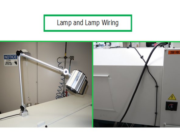
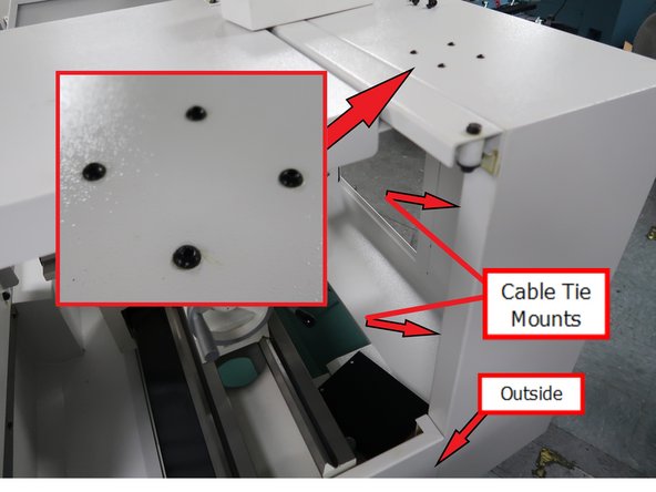
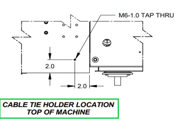
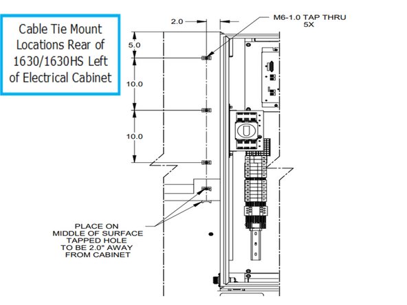
Lamp wiring is secured with Cable Tie Mounts that start at the top of the lathe behind the lamp, run down the back side near the electric cabinet and under the lathe to the bottom opening in the cabinet, Use centerpunch to mark holes.
-
-
-
Drill and tap the holes for the Cable Tie Mounts. Install Cable Tie Mounts using the correct hardware per drawing.
-
Remove Plug from the side of the headstock splash guard for the cable.
-
-
-
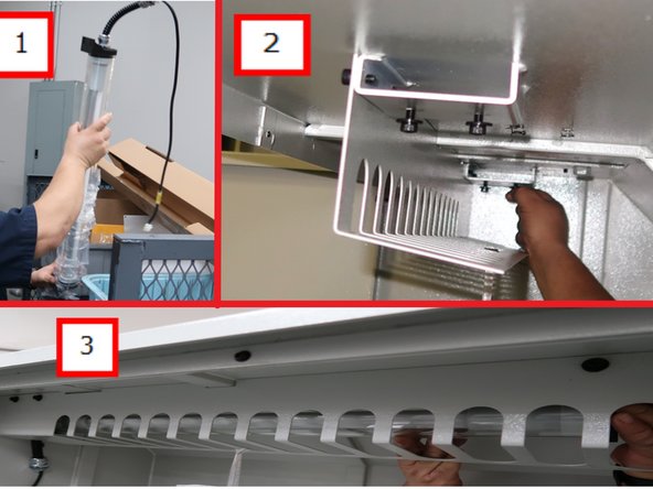
1 - Install Work Light Assembly 2 - with four screws into 3 - channel above work area.
-
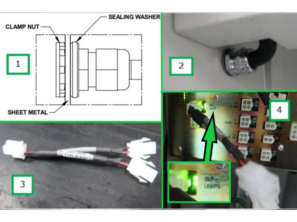
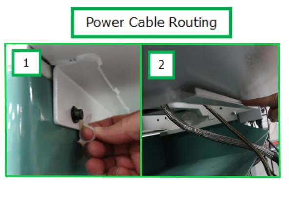
1 - Conduit connector is installed where the plug was removed. Pointed side of clamp nut is used for tightening nut. 2 -Installed view shown. 3 - Attach Extension cable single end into 4 - computer panel "OUTLIGHTS" connector. Attach Work Light Assembly cable into either connector on the other end of extension cable.
-
-
-
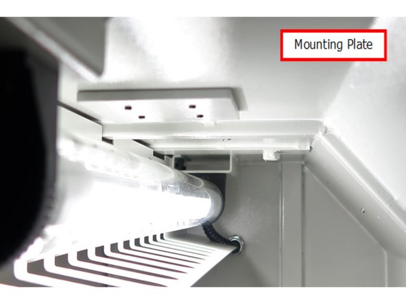
Use Mounting Plate inside of to to support Lamp.
-
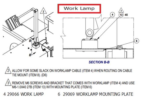
Install Lamp with screws through the Lamp base, through the sheet metal and into the Mounting Plate. Install wires with Cable Ties in the Cable Tie Mounts down the back of the lathe based upon your specific lathe.
-
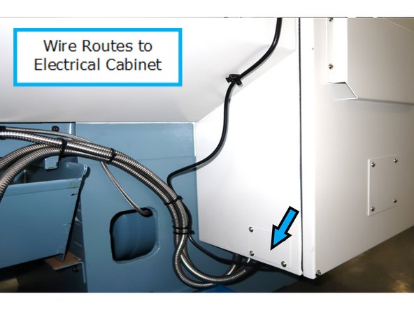
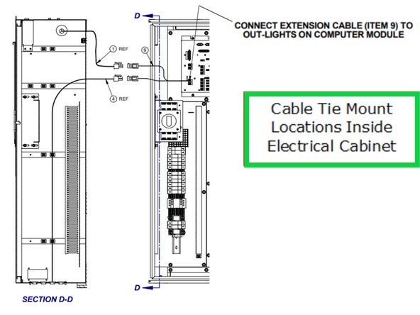
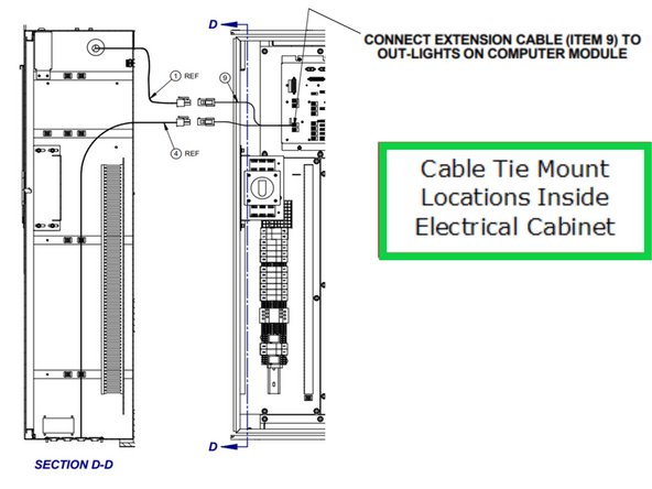
Route wires down the back and under the work area into the electrical cabinet as shown by the arrow. Wires are then routed along inside wall of electrical cabinet to the computer module and connected to the other end of the extension cable.
-
-
-
Location for the Work Lamp 26223. SHCS will be removed and replaced. Lamp is mounted here inside the lathe upside down using these holes. Two Cable Tie Mounts are installed inside channel on the inside surface to hide from view. The cable is then routed outside the lathe as shown.
-
From the side of the lathe, the cable is routed through 1 plastic grommet and then in the 2 cable way to enter the bottom of the electrical cabinet and plugged into standard outlet.
-
-
-
Work Lamp Location
-
Cable Tie Location top of 1630/1630HS
-
Cable Tie Mount Location rear of 1630/1630HS
-
-
-
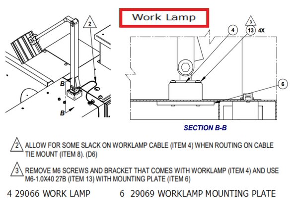
Work Lamp Details, Section B-B shows the plate installation. Notes explain replacing the supplied bolts with ones that fit the mounting plate as well as leaving slack in the wiring for lamp movement.
-
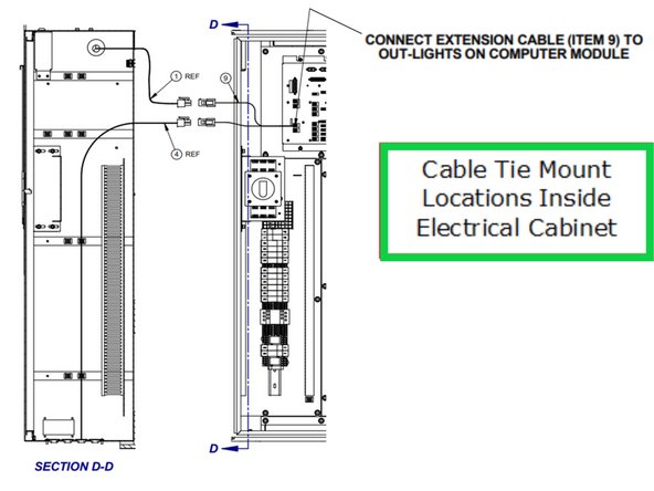
Install Work Lamp, route wiring from light, down the back, into opening in electrical cabinet. Route wiring inside electrical cabinet through existing cable mounts to be connected to "OUT-LIGHTS" connection on the computer module.
-
-
-
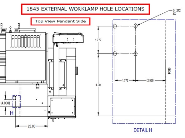
Top view of the pendant side on the left of the drawing shows the top of the 1845. Detail H shows the specific location of the Work Lamp holes.
-
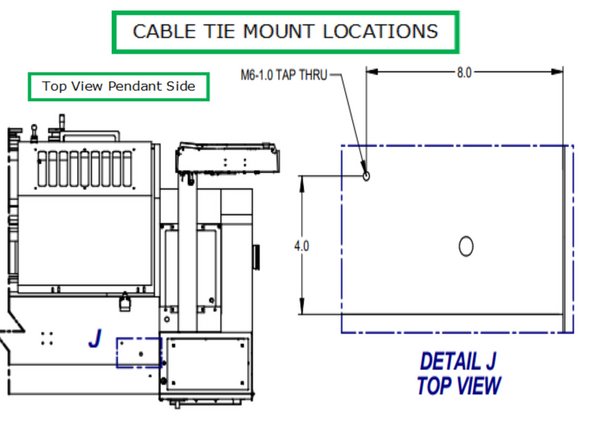
Cable Tie Location top of 1845.
-
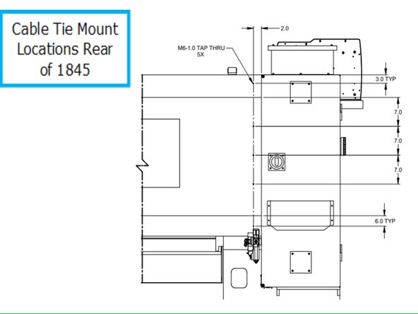
Cable Tie Mount Locations rear of 1845.
-
-
-
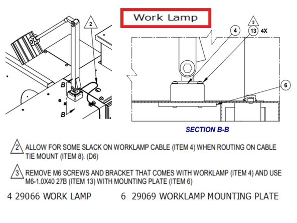
Work Lamp Details, Section B-B shows the plate installation. Notes explain replacing the supplied bolts with ones that fit the mounting plate as well as leaving slack in the wiring for lamp movement.
-
Install Work Lamp, route wiring from light, down the back, into opening in electrical cabinet. Route wiring inside electrical cabinet through existing cable mounts to be connected to "OUT-LIGHTS" connection on the computer module.
-
-
-
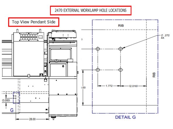
Top view of the pendant side on the left of the drawing shows the top of the 2470. Detail G shows the specific location of the Work Lamp holes.
-
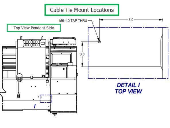
Cable Tie Location top of 2470.
-
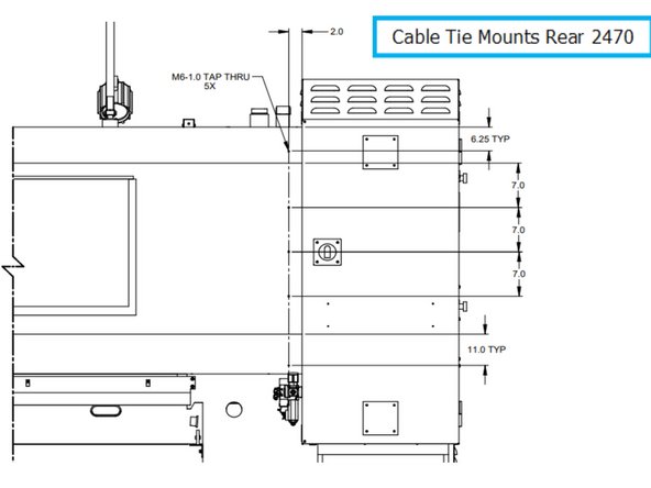
Cable Tie Mount Locations rear of 2470.
-
-
-
Work Lamp Details, Section B-B shows the plate installation. Notes explain replacing the supplied bolts with ones that fit the mounting plate as well as leaving slack in the wiring for lamp movement.
-
Install Work Lamp, route wiring from light, down the back, into opening in electrical cabinet. Route wiring inside electrical cabinet through existing cable mounts to be connected to "OUT-LIGHTS" connection on the computer module.
-


