Introduction
This procedure is designed for field installation of a Coolant Pump Option on a TRAK lathe. Wires need to be added to the electric cabinet, run the coolant hose, add the pump and check operation. Steps 1 - 6 are installation instructions for the lathe series1630, 1630HS, 1845 and 2470. Step 7 - 13 are specific to the 1440 ELX.
-
-
Power should be off at the lathe when working on the electrical cabinet.
-
Tip: easier to make small connections shown in the green step on the bench rather than in the electrical cabinet. Assemble 2 Fuse Holders with two Fuses, the Relay with the Relay Socket and and the Retaining Clips to hold the Relay in place. Remove terminal block end, add the Fuse Holders and Relay to the terminal block, replace end cap.
-
Connect the wires as shown for the Fuse Holders and Relay. They are added to the bottom of the power rail. A label to be added is supplied with the kit. The long wire is fed through the Wireway and connect as shown in the next step.
-
Long Wire is connected as shown.
-
-
-
The left side of this image shows where to connect the red and black wires to the relay in the next step.
-
Connect the red and black relay wires as shown in the previous step. Run wires through wireway on the left side of electric cabinet. The other end goes to the computer module as shown in the inset location "OUT - COOLANT PUMP".
-
From the outside of the electrical cabinet, 1 - Push cable through grommet. 2 - Route cable through wireway. 3 - Connect to relay as shown in the red step.
-
-
-
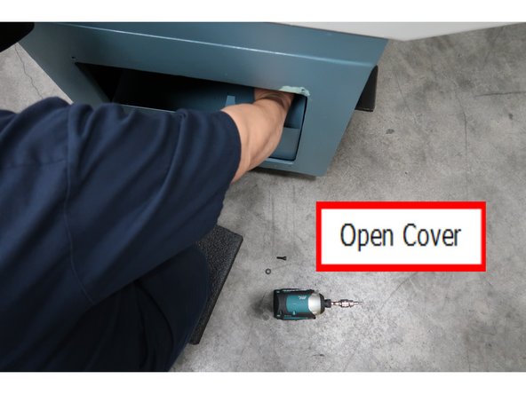
Open lower end of the lathe cabinet.
-
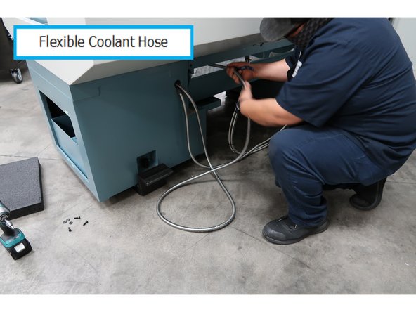
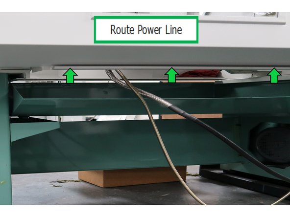
The other end of the power cable goes through opening here into pump area below lathe.
-
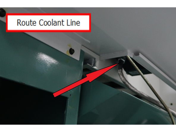
One end of the flexible hose follows the power cable into the small opening. The other end goes into the lathe work area.
-
-
-
Use Teflon tape to secure the Flexible hose.
-
Remove the electric box cover and gasket from the pump. They will be replaced in a later step.
-
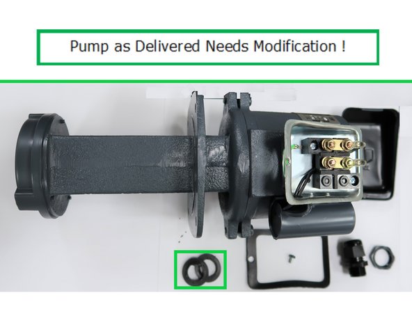
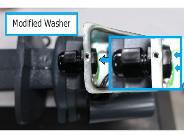
The pump as delivered needs a very important modification. The seal used to prevent liquid from entering the electric box through the wiring connection needs modification. The two washers in the highlighted box were one piece as delivered. The original one is carefully sliced down the middle and the best one is used in the next step.
-
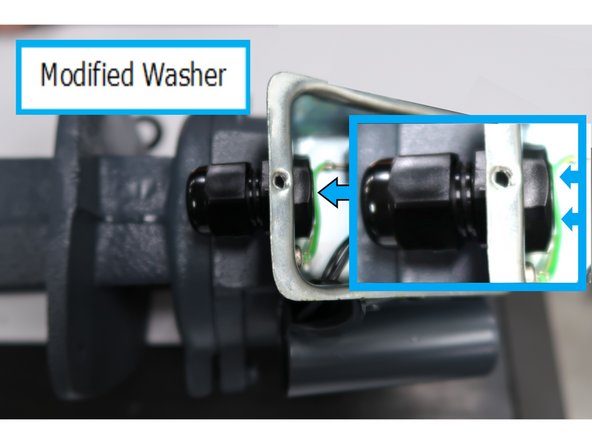
Note after cutting there are just enough threads on the liquid tight connector to fasten it securely.
-
-
-
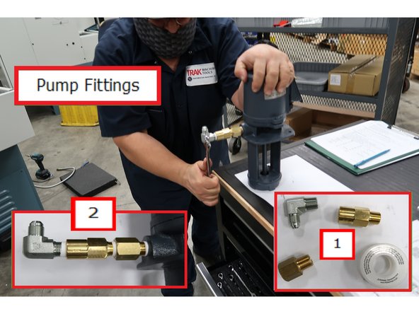
1 - Use these fittings with the Teflon tape. 2 - Like this and make them tight.
-
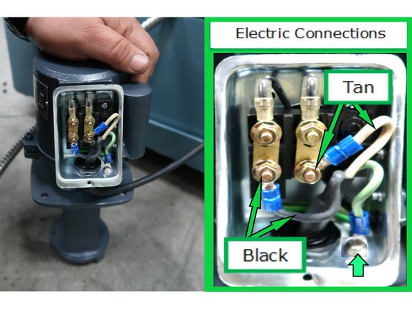
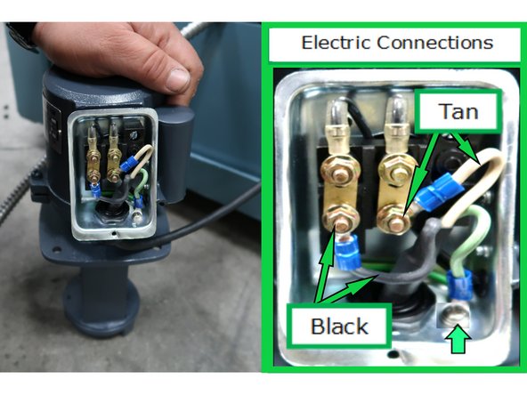
Connect the black and tan wires and don't forget the ground wire to the electrical box. Replace the gasket for the box, cover and secure it with same hardware you removed.
-
Add the coolant line from the coolant tank area to the pump, don't forget the Teflon tape. Remove the three screws and washers from the flange for the next step.
-
-
-
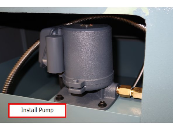
Install pump on the flange and make sure the bolts are tight.
-
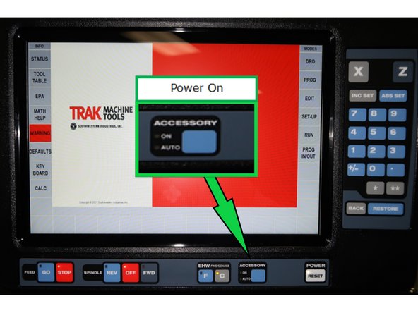
Use the Accessory button on the controller to start the pump.
-
Test Operation - Turn Lathe On:
-
Initial test to verity operation is to either listen for soft motor sound or touch for a slight vibration.
-
Secondary test is to verify operation is counterclockwise by using a flash light and check impeller.
-
Clean up coolant and electric lines by securing with tie bands as needed.
-
-
-
These instructions for the 1440ELX were done with a model of the lathe but did not complete each task. So the text and photos show and tell you what is needed but the cables and coolant hose may not show in the photos. The first thing to correct is the gasket issue with the electric connection to the pump.
-
The pump as delivered needs a very important modification. The seal used to prevent liquid from entering the electric box through the wiring connection needs modification. The two washers in the highlighted box were one piece as delivered. The original one is carefully sliced down the middle and the best one is used in the next step.
-
Note after cutting there are just enough threads on the liquid tight connector to fasten it securely.
-
-
-
Connect black and tan power wire. Don't forget the ground wire to the electric box.
-
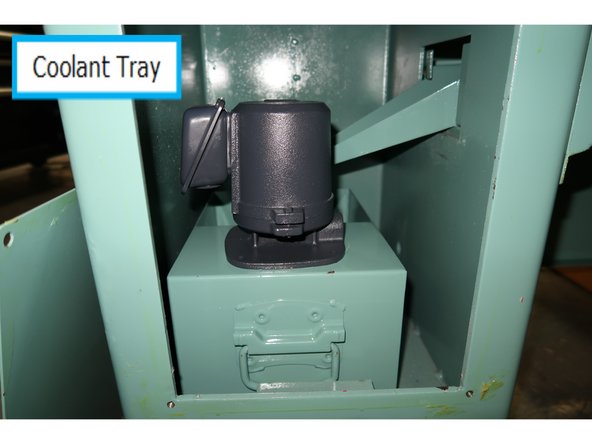
Bolt the motor to the coolant tray. Connect the coolant hose to the motor using the fitting.
-
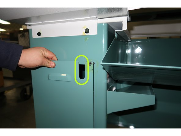
Both the coolant line and the power lines leave the coolant area through the slotted opening at the top of the cover.
-
-
-
The coolant line comes out the coolant area and gets directly routed into the bottom of the work area.
-
The coolant pump power cable gets routed through this trough all the way over to the electric cabinet. At the bottom right corner of the cabinet, there is an opening for wires. Insert the power cord through the opening and plug into the power outlet.
-
-
-
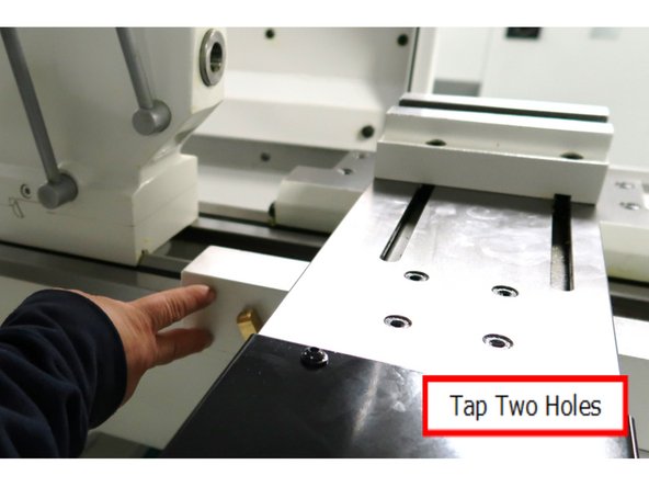
From the rear of the lathe, tap two holes for M6x20 (25B) SHCS into the back side of the saddle as shown. Parts are supplied in the kit. There is no location marked on the lathe. The important aspect is to make sure both screws are tapped straight into solid metal to support the coolant system while in use.
-
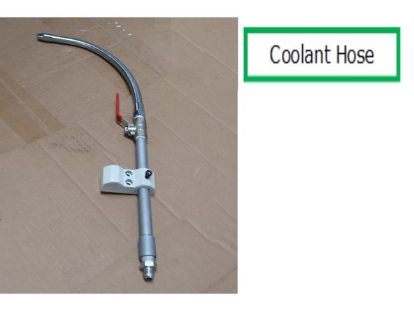
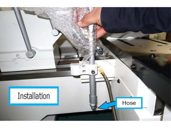
This is the coolant hose and valve that will be screwed to the rear of the saddle.
-
Here is the hose and valve shown at the location to be installed. Now you can connect the flexible hose routed from the pump into the work area to the fitting as shown. Use Teflon tape to seal the threads.
-
-
-
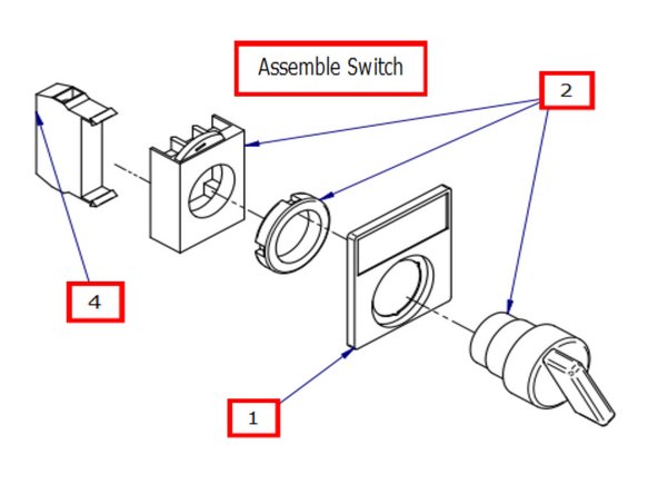
Assemble forward - reverse coolant switch and attach to apron plate. Number refer to part number in 26100 BOM. 1 - Nameplate, 2 - Two position switch assy, 4 - Contact block.
-
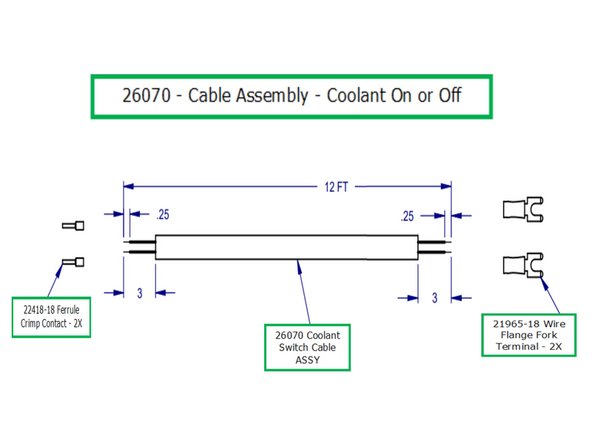
Part number 26070 the cable used to control the coolant on or off.
-
Note: The next step has you route the switch wire to the electric box through the lathe. It is up to the installer to either run the cable to the electric box first and come back to the connections here. or make the connections first.
-
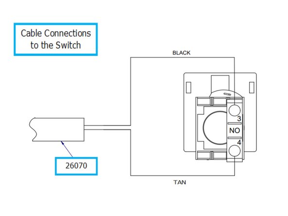
Wire the cable end to the switch as shown.
-
-
-
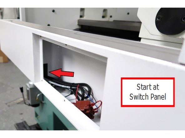
Start at the switch panel and run the control cable through this opening.
-
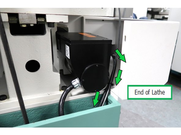
Looking from the end of the lathe, route the cable from the opening, around the motor, down in the cable channel and inside the bottom opening of the electrical cabinet.
-
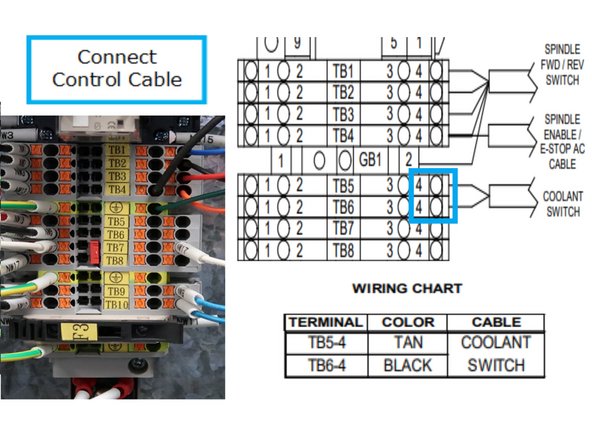
To connect the two wires, you have a photo of the location, the wiring chart, and specific location to connect the wires.
-
-
-
Test Operation - Turn Lathe On:
-
Turn on pump via switch on front of lathe.
-
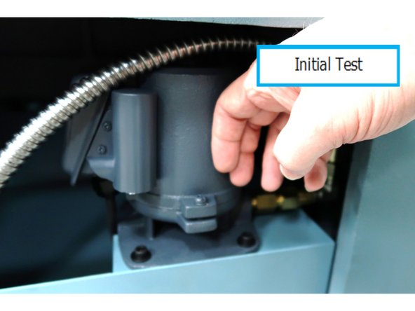
Initial test to verity operation is to either listen for soft motor sound or touch for a slight vibration.
-
Secondary test is to verify operation is counterclockwise by using a flash light to check impeller.
-


