
-
-
Jog the head down on the Z-Axis, so that the bottom counterweight hole is aligned with the column hole that is located on the right side of the machine.
-
*Note: there are two (2) counterweight holes; it is the bottom hole that must be aligned with the column hole.
-
-
-
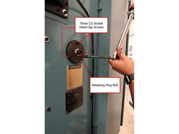
Once both the counterweight and column holes are center aligned, place the retaining plug that supports the counterweight into the column hole.
-
-
-
Using an 8 MM Hex Socket, tighten the three socket head cap screws that secure the counterweight-retaining plug into the column.
-
Using a 14 MM Allen Key, tighten the centermost bolt that secures the retaining plug to the counterweight.
-
Use a torque wrench to make sure that all three socket head cap screws and the retaining plug bolt are tightly secured into the column.
-
The torque specifications required for each screw and bolt are 25 foot-pounds.
-
-
-
Once the installation of the counterweight support is complete, make sure that the head is directly above the center of the worktable, and that the measurement for the placement of the head within the X-Axis is at equal distance on both sides.
-
Jog the head up on the Z-Axis.
-
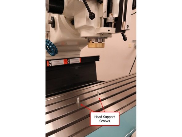
To begin the setup for the head support on the worktable, place the two (2) head support screws first directly on the worktable surface beneath the head (see image on the left).
-
-
-
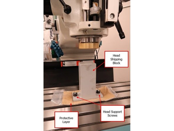
Install the entire head shipping block set onto the worktable by placing the protective layer first above the head support screws.
-
Place the head shipping block above the protective layer, and then secure the block tightly onto the head support screws.
-
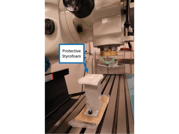
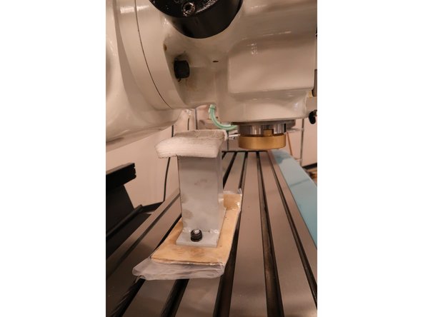
Place the protective Styrofoam above the head shipping block.
-
-
-
Move the head back on the Y-Axis until the top of the head shipping block is aligned with the area where the ram meets the head (see image on the left).
-
-
-
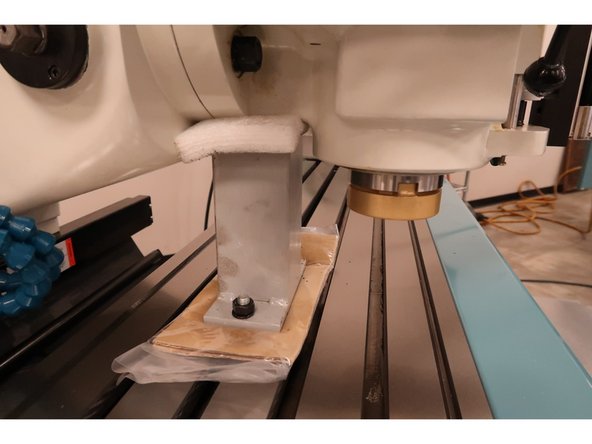
Jog the head down slowly on the Z-Axis until it bears down on the protective Styrofoam on top of the head shipping block.
-
-
-
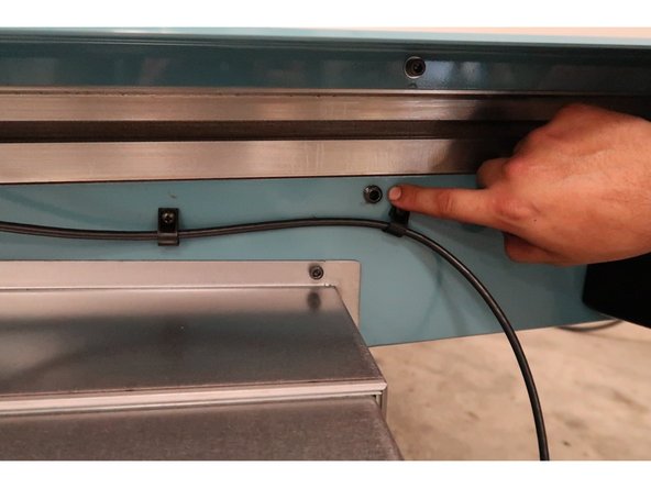
Once the head is tightly secured onto the head shipping block, use a 6 MM Socket to lock down the X Axis gibs tightly.
-
-
-
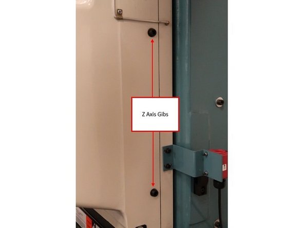
Use an 8 MM Socket to lock down the Z-Axis gibs tightly.
-
-
-
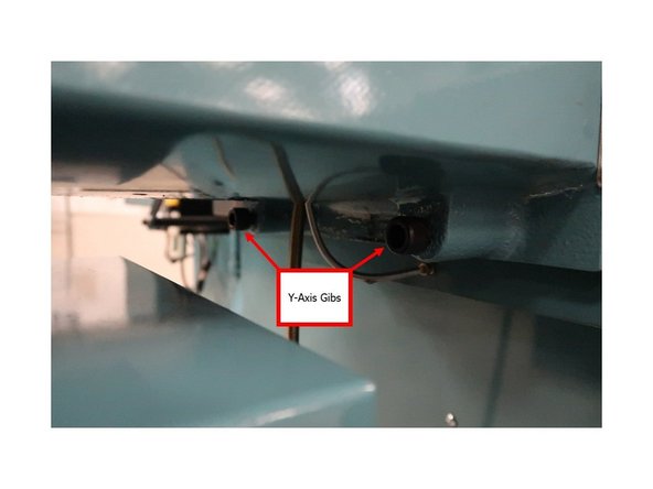
Use a 10 MM Allen Key to lock down the Y-Axis gibs tightly.
-


Cancel: I did not complete this guide.
One other person completed this guide.