
Tools
Parts
No parts specified.
-
-
Align and center both counterweight holes to the column holes. You should be able to insert the two counterweight support rods through these holes without any obstructions.
-
-
-
Begin inserting the two steel rods (with flanges) through the column holes (see image on the left):
-
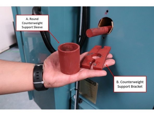
First, install the round counterweight support sleeve (shown on the image as “A”) into the column hole before inserting the rod.
-
With the first steel rod, hold the part of the rod with the welded end (shown on the image as “B”), and insert the non-welded end through the round counterweight support sleeve in the column hole.
-
-
-
On the other side of the column, attach the counterweight support sleeve and bracket to the other end of the steel rod (see image on the left):
-
First, install the round counterweight support sleeve (shown on the image as “A”) through the rod and into the column hole.
-
Next, install the counterweight support bracket (shown on the image as “B”) through the rod and against the column.
-
When installing the support bracket against the column, make sure that the slots on the bracket are aligned with the designated area for the counterweight support screw holes on the column.
-
-
-
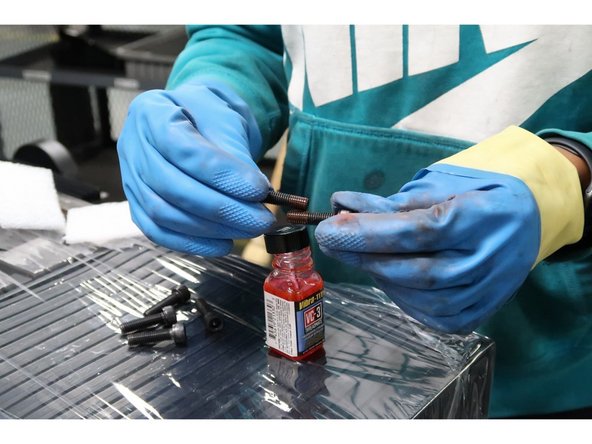
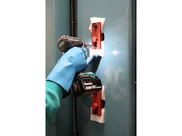
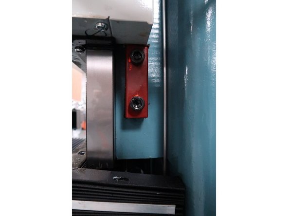
Apply threadlocker (Loctite Blue 242 or equivalent) on the counterweight support screws to help keep them in place inside the column. Doing so will prevent possible vibration damage to the screws during transit.
-
-
-
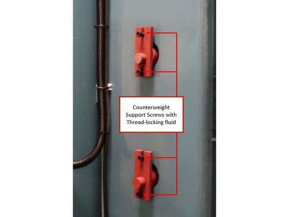
Place the counterweight support screws (which should have thread-locking fluid on them) through the counterweight support bracket, and into their designated holes into the column.
-
Do not screw them into the column yet during this step.
-
-
-
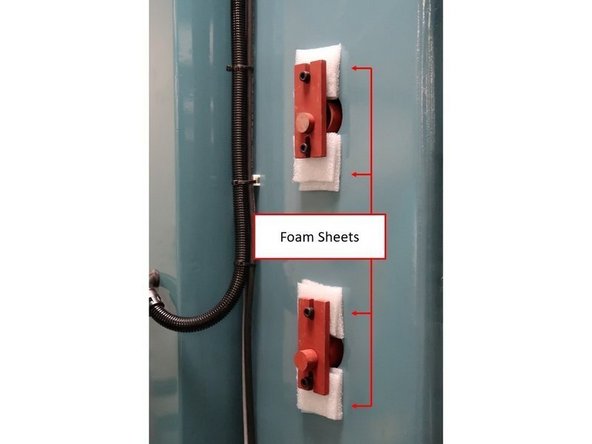
Place foam sheets behind each counterweight bracket against the column to prevent the bracket itself from scratching the column’s paint.
-
-
-
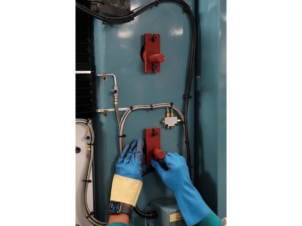
Using a 6 MM Hex Socket, center screw the counterweight support brackets into the column, and make sure that the counterweight support is held tightly.
-
-
-
Make sure that the counterweight support brackets are tightly secured on both sides of the column.
-
Repeat Steps #4 – 7 above on the opposite side of the column in order to ensure that the two counterweight supports are completely supported on both sides.
-
-
-
Once the installation of the counterweight support is complete, make sure that the head is directly above the center of the worktable, and that the measurement for the placement of the head within the X-Axis is at equal distance on both sides.
-
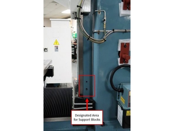
Jog the head all the way up on the Z-Axis, and ensure that the designated holes for the support blocks on both sides of the Z Way Surface are completely visible and unobstructed.
-
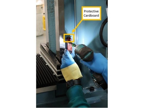
Place foam or cardboard in between both the support blocks and the Z Way Surface on both sides of the machine to prevent damage.
-
Using an 8 MM Hex Socket, center screw both support blocks on both sides of the Z Way Surface, and make sure that both sides are tightly secured.
-
Slowly jog the head down on the Z-Axis until the two support blocks on both sides prevent the head from moving down any further.
-
-
-
Moving on to the gibs section on the Z-Axis, use a 10 MM Hex Socket to center screw the two gib screws tightly.
-
-
-
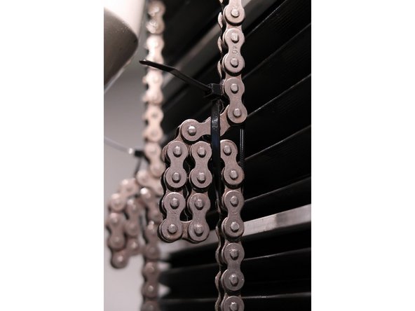
Gather the extra slack, and place zip ties on both of the counterweight chains.
-


Cancel: I did not complete this guide.
One other person completed this guide.