Introduction
The 0 degree setting for the live tool spindle can shift after the live tool spindle motor is reinstalled. To orient the live tool spindle so live tool changes occur smoothly, adjust the reference distance correction parameter 34090. This procedure explains how to find the new value of 34090.
On the TC820LTY-S the live tool spindle encoder is incremental, so the spindle has no absolute position reference on power-up. That is why the reference offset in 34090 must be re-established after a motor reinstall. The standard TC820LTY uses an absolute encoder and does not require this.
-
-
After the live tool spindle motor is reinstalled, commanding the spindle to 0 degree may no longer align it for live tool change.
-
The encoder zero no longer matches the mechanical zero, so the commanded 0 position is mechanically wrong for tool change. This is the condition the procedure corrects.
-
-
-
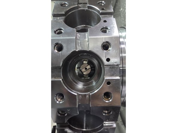
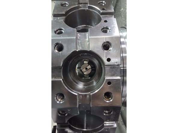
Disable the spindle by pressing SPINDLE STOP (red button on the MCP). Move the spindle by hand so the notch is aligned for smooth live tool changes.
-
-
-
Go to [Diagnostics] → [Axis Diag] → [Service axis.] → Press [Axis+] until AX8 is selected.
-
Find the "Actual pos. value measuring system 1" row and write down its value. You will use this number in Step 4.
-
In this example the value is 57.754 degrees.
-
-
-
Enter the manufacturer password.
-
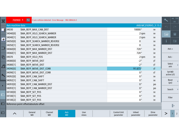
Go to [Setup] → [Machine data] → [Axis MD], and search for 34090.
-
There are two ways to calculate the new value for 34090:
-
Spindle moved clockwise to reach the desired orientation: new 34090 = original value + reading from Step 3
-
Spindle moved counterclockwise to reach the desired orientation: new 34090 = original value − reading from Step 3
-
Spindle CW and CCW direction is determined by standing parallel to the live tool spindle and looking at the machine door.
-
In this example the spindle was moved clockwise, so: new 34090 = 33.919 (original) + 57.754 = 91.673
-
Enter the new value for 34090, then power cycle the machine.
-
-
-
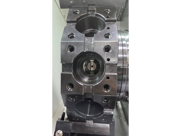
Go to the TSM screen and orient the live tool spindle to the 0 position. Confirm the spindle notch is perfectly aligned for tool changes.
-
Perform a few tool changes with live tool and ensure that tool changes are not loud.
-
![Go to [Diagnostics] → [Axis Diag] → [Service axis.] → Press [Axis+] until AX8 is selected.](https://d3t0tbmlie281e.cloudfront.net/igi/trakmtsupport/csWaq2RNgLCJvXnB.medium)

Team
