Introduction
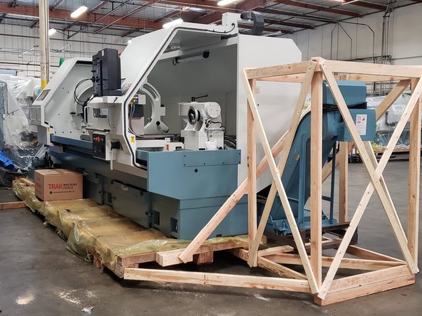
This guide details the FST installation procedures for reinstalling the Hydraulic 8 Tool Turret to the TRAK TRL 30120RX after they have been shipped together to the client site, removed from the pallet, and are ready for operation.
Please note that with this procedure, the wiring for the electrical cabinet and the final Turret Assembly are already completed at the factory. The Hydraulic System has been disconnected from the machine during shipping, and the FST will be responsible for reconnecting them all at the client site.
-
-
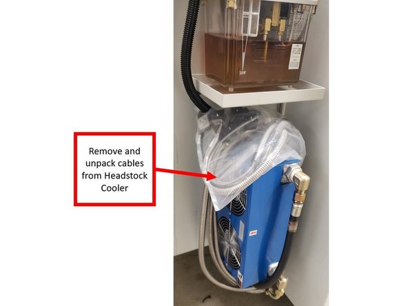
Remove and unpack the cables that were initially wrapped around the Headstock Cooler during shipping.
-
Install the Solenoid connectors on the Solenoid Valve Body and Sensor Body on top of the Hydraulic System (P/N: 31192), as indicated in the image.
-
-
-
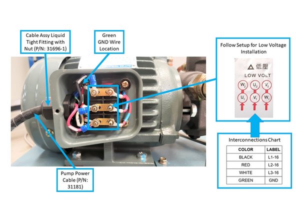
Install the Pump Power Cable (P/N: 31181) to the Terminal Box along with its Liquid Tight Fitting with Nut, as shown on the image.
-
There will be wires coming from within the terminal box with the following labels: U1, U2, V1, V2, W1, and W2, along with label instructions for both high and low voltage installation. As shown on the image, follow the instructions for low voltage installation:
-
Top row: combine the black wire (L1-16) with the U1 wire on the left, and set the W2 wire on the right.
-
Second row: combine the red wire (L2-16) with the V1 wire on the left, and set the U2 wire on the right.
-
Bottom row: combine the white wire (L3-16) and the W1 wire on the left, and set the V2 wire on the right.
-
Install the Green GND Wire to its location on the top left screw inside the terminal box, as shown on the second image on the left.
-
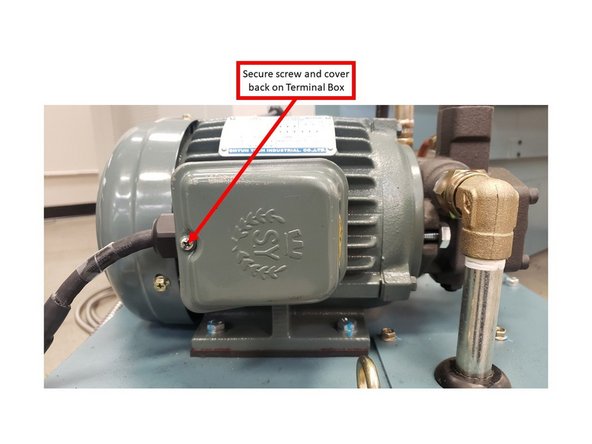
Once the Pump Power Cable is properly installed inside the Terminal Box, secure the screw and cover back on the Terminal Box on the Hydraulic System.
-
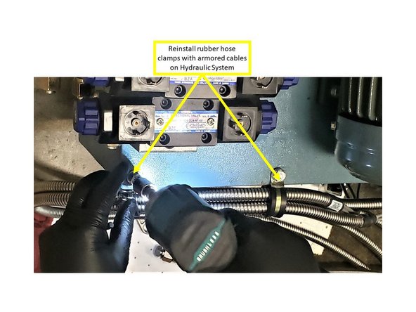
Reinstall the rubber hose clamps (which were grouping the Pump Power Cable, and the Clamp + CW [P/N: 31234] and Pressure + Unclamp + CCW [P/N: 31233] Armored Cables together) on the side of the Hydraulic System, as shown on the image.
-
-
-
Unwrap the four (4) Hydraulic Hoses that were wrapped in foam and stored inside the machine, and begin installing them to their designated locations.
-
Remove the four Hydraulic Hose Plugs (P/N: 34087) and Caps (P/N: 34086) from both the Hydraulic Hoses and the fittings on the Hydraulic System.
-
Reinstall the Hydraulic Hoses back into their respective fittings on the Hydraulic System, as shown on the image.
-
-
-
Turn ON the Hydraulic Pump Circuit Breaker (P/N: 31590-4) in the electrical cabinet.
-
Once the Hydraulic 8 Tool Turret has been reconnected to the machine, turn the power ON, and then release the E-Stop.
-
-
-
When you have completed the installation, and want to continue with the testing process, the link below will guide you to:
-
-
Hitting the browser Back button will return you to: 30120RX Hydraulic 8 Tool Turret - FST Installation of 8 Tool Turret with Machine After Shipping
-