VMCsi Transformer Option Requirements
All TRAK VMCsi models require 480VAC power for operation. The VMC7si and VMC10si can accept standard 208V three-phase input power (198–218V acceptable) connected to L1, L2, and L3 at the input breaker.
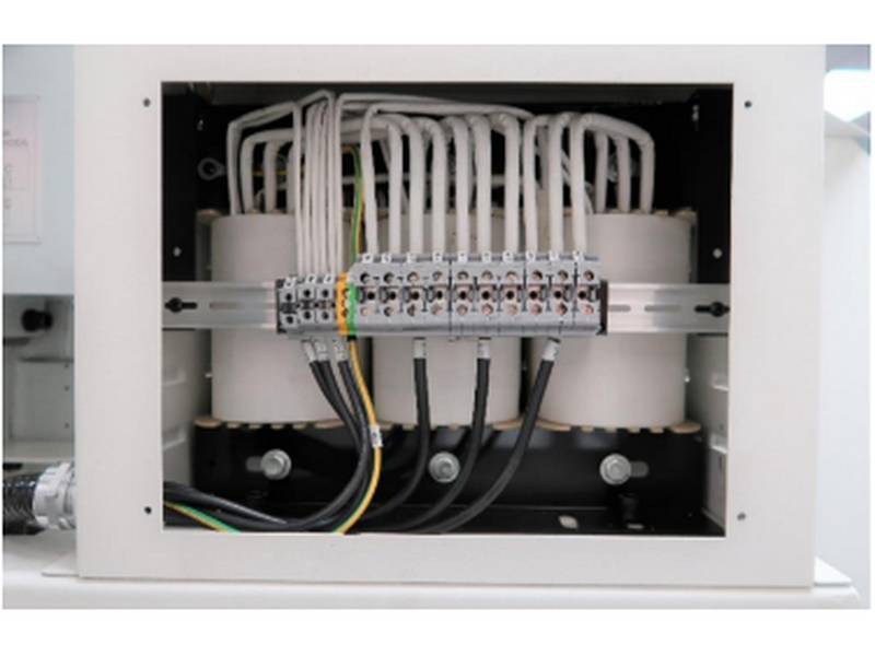
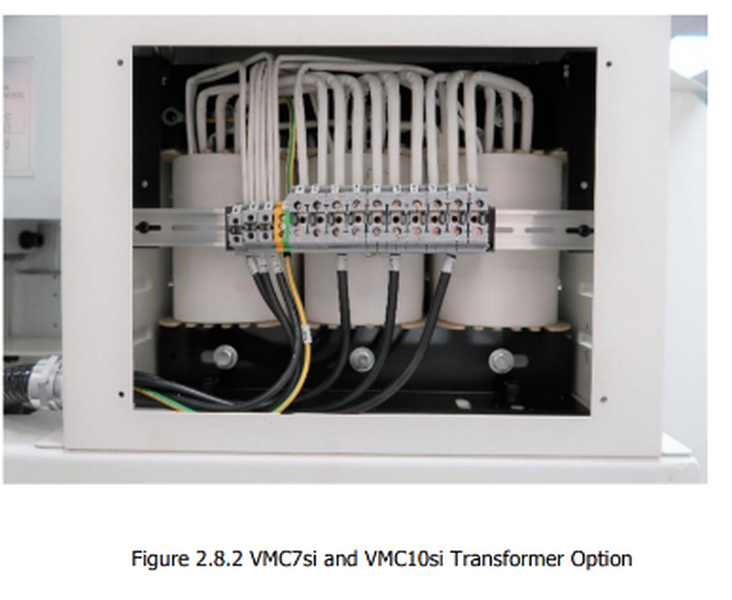
If the customer only has 208V power available, a step-up transformer must be used to convert 208V to 480V. The optional transformer for VMC7si/VMC10si customers is shown in Figure 2.8.2. This transformer steps up 208V input power to 480V output.
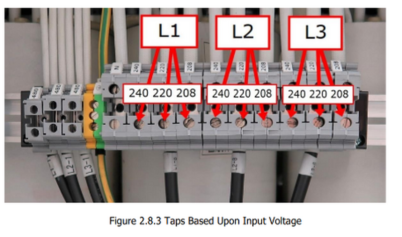
The transformer includes three voltage taps: 208V, 220V, and 240V. The installer should measure the incoming voltage and connect L1, L2, and L3 to the appropriate tap corresponding to the nearest available voltage at the customer’s facility. See Figure 2.8.3 for details.
TCsi Transformer Option Requirements
The TCsi machines require 480VAC power for operation. If the customer only has 208–240VAC incoming power, a step-up transformer must be used to achieve 480VAC. TRAK offers an optional transformer for this purpose.
The transformer connects directly to the customer’s incoming power and provides three tapped voltage settings: 208VAC, 220VAC, and 240VAC. These taps are located underneath the cover on top of the electrical cabinet, mounted on the transformer.
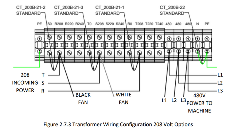
All machines leave the factory preconfigured for 208V. Use the following table to select the correct voltage tap based on the incoming power:
Transformer Tap Selection (TCsi)
| Incoming Voltage Range | Tap to Use on Transformer |
|---|---|
| 200–215V | 208V |
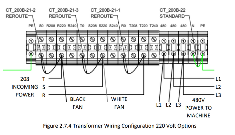
| 216–225V | 220V |
| 225–240V | 240V |
Figure 2.7.3 shows the transformer’s default factory wiring for 208VAC incoming power. In this configuration, the taps are jumpered from each selected voltage leg to S0, T0, and R0, and the fan is wired to the R (black wire) and S (white wire) terminals.
If the customer’s incoming voltage is 216–225V, follow the wiring diagram shown in Figure 2.7.4.
If the customer’s incoming voltage is 225–240V, follow Figure 2.7.5.
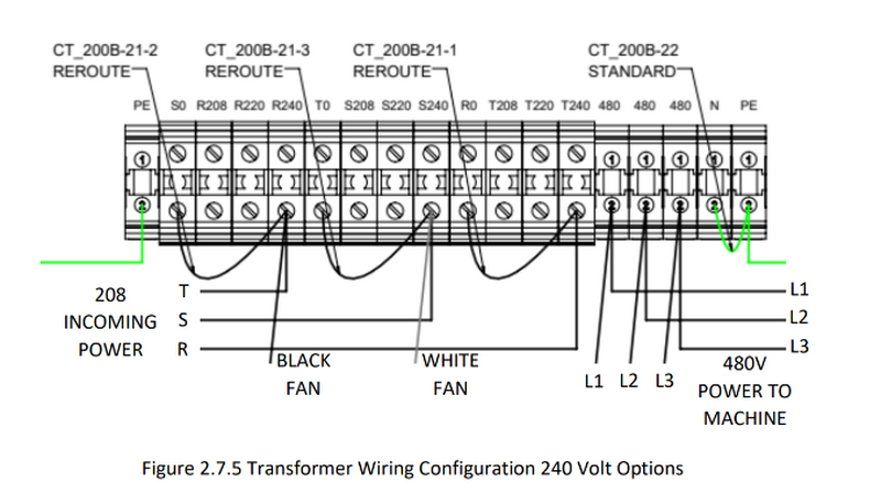
For each voltage adjustment, ensure that both the jumper and fan wires are moved so that each leg connects to the appropriate tap (S0, T0, R0) for the incoming voltage.
0 Comments